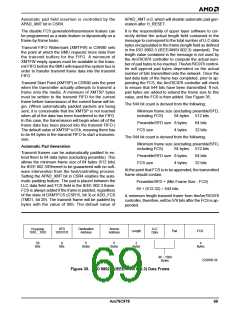
46 – 1500
Bytes
56
Bits
8
Bits
6
6
2
4
Bytes
Bytes
Bytes
Bytes
Preamble
1010....1010
SFD
10101011
Destination
Address
Source
Address
LLC
Data
Length
Pad
FCS
1 – 1500
Bytes
45 – 0
Bytes
Start of Frame
at Time = 0
Bit
0
Bit Bit
Bit
7
7
0
Increasing Time
Most
Significant
Byte
Least
Significant
Byte
22206B-39
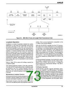
Figure 36. IEEE 802.3 Frame and Length Field Transmission Order
voked. This is to be backwards compatible to the
C-LANCE (Am79C90) software.
Loopback Operation
Loopback is a mode of operation intended for system
diagnostics. In this mode, the transmitter and receiver
are both operating at the same time so that the
Am79C978 controller receives its own transmissions.
The Am79C978 controller provides two basic types of
loopback. In internal loopback mode, the transmitted
data is looped back to the receiver inside the
Am79C978 controller without actually transmitting any
data to the external network. The receiver will move the
received data to the next receive buffer, where it can be
examined by software. Alternatively, in external loop-
back mode, data can be transmitted to and received
from the PHY.
Since the Am79C978 controller has two FCS genera-
tors, there are no more restrictions on FCS generation
or checking, or on testing multicast address detection
as they exist in the half-duplex PCnet family devices
and in the C-LANCE. On receive, the Am79C978 con-
troller now provides true FCS status. The descriptor for
a frame with an FCS error will have the FCS bit (RMD1,
bit 27) set to 1. The FCS generator on the transmit side
can still be disabled by setting DXMTFCS (CSR15, bit
3) to 1.
In internal loopback operation, the Am79C978 control-
ler provides a special mode to test the collision logic.
When FCOLL (CSR15, bit 4) is set to 1, a collision is
forced during every transmission attempt. This will re-
sult in a Retry error.
Refer to Table 30 for various bit settings required for
Loopback modes.
The external loopback requires a two-step operation.
The internal PHY must be placed into a loopback mode
by writing to the PHY Control Register (BCR33,
BCR34). Then, the Am79C978 controller must be
placed into an external loopback mode by setting the
Loop bits.
Full-Duplex Operation
TheAm79C978 controller supports full-duplex opera-
tion on the 10BASE-T and MII interfaces. Full-duplex
operation allows simultaneous transmit and receive ac-
tivity. Full-duplex operation is enabled by the FDEN bit
located in BCR9. Full-duplex operation is also enabled
through Auto-Negotiation when DANAS (BCR 32, bit 7)
is not enabled and the ASEL bit is set, and itslinkpartner
is capable of Auto-Negotiation and full-duplex opera-
tion.
Miscellaneous Loopback Features
All transmit and receive function programming, such as
automatic transmit padding and receive pad stripping,
operates identically in loopback as in normal operation.
Runt Packet Accept is internally enabled (RPA bit in
CSR124 is not affected) when any loopback mode is in-
Am79C978
73

 AMD [ AMD ]