AMD
P R E L I M I N A R Y
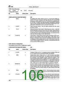
TCR2: Clock Recovery
This
register
is
the
Clock
Recovery
Configuration register.
Bit Name
Reset Value
Description
CONFIGURATION REGISTER INDEX:
02h
7
WNS2
0
Bit Stuffing Start. When WNS2 is set to a 1, then the bit stuffing op-
eration on RX and TX frames will begin after the PHY header field
has passed. When WNS2 is set to a 0, then the bit stuffing function
on RX and TX frames will begin operation immediately following
Start of Frame Delimiter detection. Note that bit stuffing may be dis-
abled with control bits in TCR1 (TX) and TCR3 (RX).
6
5
CLKRS
ECLK
0
0
Clock Recovery Select. This bit selects between the two clock
recovery circuits.
External Receive Clock Select. When this bit is set to 1, then the
device will expect a receive clock on the RXCIN pin. When this bit is
set to a 0, then the internal clock recovery circuit selected by the
CLKRS bit will be used to internally generate a recovered receive
clock from the incoming receive data stream.
4:0
CLKP[4:0]
0
Clock Phase. These bits are used to select the phase of the recov-
ered RX clock relative to the RX data edges. Valid values are 0
through 19 decimal, where each bit of resolution represents a shift
in the phase of the sample point by one CLKIN period when the
CLKGT20 bit of MIR9 is set to 0, and two CLKIN periods when the
CLKGT20 bit of MIR9 is set to 1.
TCR3: Receive Configuration
This register is the Receive Configuration register.
CONFIGURATION REGISTER INDEX: 03h
Bit
Name
Reset Value
Description
7
6
LOOPB
WNS
0
0
Loopback. When set to a 1, a loopback mode is enabled. When set
to a 0, normal receive and transmit paths are followed.
Endian Mode Select. When set to a 1, this bit selects big endian
(MS bit first) as the data format. The setting of this bit only affects
the operation of the parallel-to-serial conversion register in the
transmit path and the serial-to-parallel conversion register in the re-
ceive path. No other areas are affected, i.e., start of frame detection
is always performed on the bit stream as it will appear on the me-
dium. When set to 0, little endian mode (LS bit first) is selected.
5
RXENDCB
0
Receive Enable DC Bias Control. When RXENDCB is set to a 1,
then the receive machine will automatically remove the DC Bias
Control effects from the input data stream. When RXENDCB is
reset to a 0, then the receive stream DC Bias removal circuit will
be disabled.
4
RXDI
0
0
Receive Data Invert. When set to a 1, the incoming receive serial
data stream is inverted. When set to a 0, the incoming receive serial
data stream is not inverted.
3:0
PFL[3:0]
Physical layer Field Length [3:0]. These bits are used to determine
the number of bytes of PHY header that are allowed to pass before
the Am79C930 device begins calculating the CRC8 and CRC32
and DC bias control. The Physical layer Field Length value is used
106
Am79C930

 AMD [ AMD ]