Revision 1.02 – April 12, 2007
S5920 – PCI Product: Electrical Characteristics
Data Book
TIMING SPECIFICATION
PCI Clock Specification
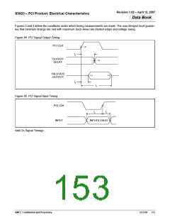
Table 5 summarizes the A. C. characteristics for the PCI bus signals as they apply to the S5920. The figures after
Table 5 visually indicate the timing relationships.
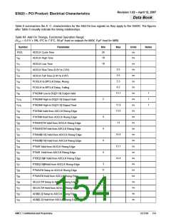
Table 63. Functional Operation Range
(V = 5.0V ± 5%, 0°C to 70°C, 50 pF load on outputs for MAX, 0 pF load for MIN)
CC
Symbol
Parameter
Min
Max
Units
Notes
T
30
ns
Clock Time
cyc
t
t
t
t
11
11
1
ns
ns
CLK High Time
CLK Low Time
1
2
3
4
4
4
V/ns
V/ns
ns
Rise Time (0.8V to 2.0V)
Fall Time (2.0V to 0.8V)
1
1
1
CLK to Signal Valid Delay (Bused Signals)
CLK to Signal Valid Delay (Point-to-Point Signals)
2
2
11
12
t
1,2
5
t
t
t
t
2
ns
ns
ns
ns
Float to Active Delay
3
3
4
4
6
7
8
9
28
Active to Float Delay
7
0
Rising Edge Setup
Hold from PCI Clock Rising Edge
Notes:
1. Rise and fall times are specified in terms of the edge rate measured in V/ns. This slew rate is met across the minimum peak-to-peak portion
of the clock waveform as shown in Figure 1.
2. Minimum times are evaluated with 0 pF equivalent load; maximum times are evaluated with 50 pF equivalent load.
3. For purposes of Active/Float timing measurements, the Hi-Z or 'off" state is defined to be when the total current delivered through the compo-
nent pin is less than or equal to the leakage current specification.
4. See the timing measurement conditions in Figure 3.
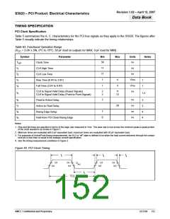
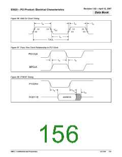
Figure 83. PCI Clock Timing
t1
t3
t4
2.0
2.0
0.8
2.0
0.8
2.0
0.8
VIH2
0.8
t2
TCL
AMCC Confidential and Proprietary
DS1596
152

 AMCC [ APPLIED MICRO CIRCUITS CORPORATION ]