Revision 1.02 – April 12, 2007
S5920 – PCI Product: Pass-Thru Operation
Data Book
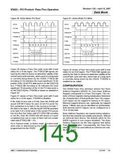
S5920 Base Address Register Definition
PCI BIOS will not allocate the I/O space and will prob-
ably disable the region.
Certain bits in the Base Address Register have spe-
cific functions:
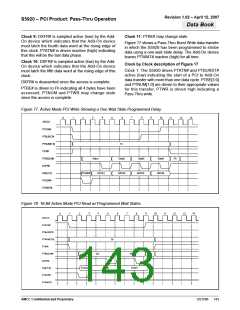
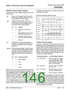
Figure 82. 8-Bit Active Mode PCI Write
Memory or I/O mapping. If this bit is clear, the
region should be memory mapped. If this bit is
set, the region should be I/O mapped.
D0
1
2
3
4
5
6
7
ADCLK
PTATN#
PTBURST#
PTNUM[1:0]
PTWR
Location of a memory region. These bits
D2:1
request that the region be mapped in a particu-
lar part of memory. These bit definitions are
only used for memory mapped regions.
1h
D2
D1
Location
PTBE[3:0]
DXFR#
0
0
Anywhere in 32-bit memory
space
Eh
Dh
Bh
7h
Fh
0
1
1
1
0
1
Below 1 Mbyte in memory space
(Real Mode address space)
DQ[7:0]
PTADDR Byte0 Byte1 Byte2 Byte3
PTWAIT#
PTADR#
Anywhere in 64-bit memory
space (not valid for the S5920)
Reserved
Prefetchable. For memory mapped regions,
the region can be defined as cacheable. If set,
the region is cacheable. If this bit is clear, the
region is not.
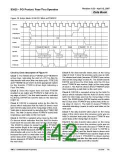
Creating a Pass-Thru Region
D3
Section 3.11 describes the values that must be pro-
grammed into the non-volatile boot device to request
various block sizes and characteristics for Pass-Thru
regions. After reset, the S5920 downloads the con-
tents of the boot device locations 54h, 58h, 5Ch, and
60h into “masks” for the corresponding Base Address
Registers. The following are some examples for vari-
ous Pass-Thru region definitions:
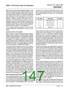
Pass-Thru region bus width. These two bits are
used by the S5920 to define the data bus width
for a Pass-Thru region. Regardless of the pro-
gramming of other bits in the BADR register, if
D31:30 are zeros, the Pass-Thru region is dis-
abled.
D31:30
NV Memory Contents
Pass-Thru Region Definition
D31 D30 Add-On Bus Width
54h = BFFFF002h
Pass-Thru region 1 is a 4 Kbyte
region, mapped below 1 Mbyte
in memory space with a 16-bit
Add-On data bus. This memory
region is not cacheable.
0
0
1
1
0
1
0
1
Region disabled
8 bits
16 bits
58h = 3xxxxxxxh
5Ch = FFFFFF81h
60h = 00000000h
Pass-Thru region 2 is disabled.
(D31:30 = 00.)
32 bits
Pass-Thru region 3 is a 32-bit,
128 byte I/O-mapped region.
BADR1:4 bits D31:30 are used only by the S5920.
When the host reads the Base Address Registers dur-
ing configuration cycles, they always return the same
value as D29. If D29 is zero, D31:30 return zero, indi-
cating the region is disabled. If D29 is one, D[31:30]
return one. This operation limits each Pass-Thru
region to a maximum size of 512 Mbytes of memory.
Pass-Thru region 4 is disabled.
During the PCI bus configuration, the host CPU writes
all ones to each Base Address Register, and then
reads the contents of the registers back. The mask
downloaded from the boot device determines which
bits are read back as zeros and which are read back
as ones. The number of zeros read back indicates the
amount of memory or I/O space a particular S5920
Pass-Thru region is requesting.
For I/O mapped regions, the PCI specification allows
no more than 256 bytes per region. The S5920 allows
larger regions to be requested by the Add-On, but a
AMCC Confidential and Proprietary
DS1596
146

 AMCC [ APPLIED MICRO CIRCUITS CORPORATION ]