MAX II Architecture
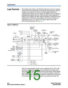
asynchronous load data input comes from the data3input of the LE. For
combinational functions, the LUT output bypasses the register and drives
directly to the LE outputs.
Each LE has three outputs that drive the local, row, and column routing
resources. The LUT or register output can drive these three outputs
independently. Two LE outputs drive column or row and DirectLink
routing connections and one drives local interconnect resources. This
allows the LUT to drive one output while the register drives another
output. This register packing feature improves device utilization because
the device can use the register and the LUT for unrelated functions.
Another special packing mode allows the register output to feed back into
the LUT of the same LE so that the register is packed with its own fan-out
LUT. This provides another mechanism for improved fitting. The LE can
also drive out registered and unregistered versions of the LUT output.
LUT Chain & Register Chain
In addition to the three general routing outputs, the LEs within an LAB
have LUT chain and register chain outputs. LUT chain connections allow
LUTs within the same LAB to cascade together for wide input functions.
Register chain outputs allow registers within the same LAB to cascade
together. The register chain output allows an LAB to use LUTs for a single
combinational function and the registers to be used for an unrelated shift
register implementation. These resources speed up connections between
LABs while saving local interconnect resources. See “MultiTrack
Interconnect” on page 2–15 for more information on LUT chain and
register chain connections.
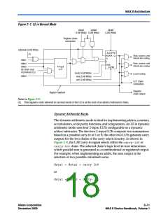
addnsub Signal
The LE’s dynamic adder/subtractor feature saves logic resources by
using one set of LEs to implement both an adder and a subtractor. This
feature is controlled by the LAB-wide control signal addnsub. The
addnsubsignal sets the LAB to perform either A + B or A – B. The LUT
computes addition; subtraction is computed by adding the two’s
complement of the intended subtractor. The LAB-wide signal converts to
two’s complement by inverting the B bits within the LAB and setting
carry-in to 1, which adds one to the least significant bit (LSB). The LSB of
an adder/subtractor must be placed in the first LE of the LAB, where the
LAB-wide addnsubsignal automatically sets the carry-in to 1. The
Quartus II Compiler automatically places and uses the adder/subtractor
feature when using adder/subtractor parameterized functions.
Altera Corporation
December 2006
Core Version a.b.c variable
2–9
MAX II Device Handbook, Volume 1

 ALTERA [ ALTERA CORPORATION ]