Chapter 17: Understanding and Evaluating Power in MAX II Devices
17–9
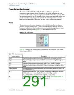
PowerPlay Early Power Estimator Inputs
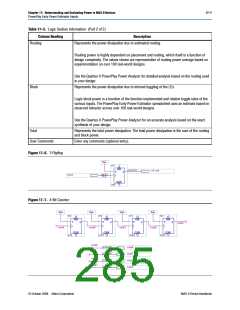
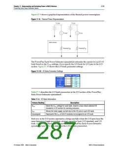
Figure 17–9 shows a graphical representation of the thermal power consumption.
Figure 17–9. Thermal Power Representation
V
V
CCIO
CCINT
I
I
CCIO
CCINT
MAX II Device
Thermal P
Thermal P
IO
INT
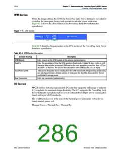
The PowerPlay Early Power Estimator spreadsheet estimates the current for each I/O
bank based on the VCCIO settings, if you specify the I/O bank for I/O pins in the I/O
section. Figure 17–10 shows the I/O bank parameter settings.
Figure 17–10. I/O Bank Parameter Settings
Table 17–5 describes the I/O bank parameters in the I/O section of the PowerPlay
Early Power Estimator spreadsheet.
Table 17–5. I/O Bank Information
Column Heading
Description
VCCIO
Select the VCCIO voltage for each bank. Used to cross-check selected I/O
standards in I/O section for warning purposes.
ICCIO
Shows the total supply current due to the I/O pins in each I/O bank.
Represents the ICCIO of all I/O modules not assigned to an I/O bank.
Unassigned
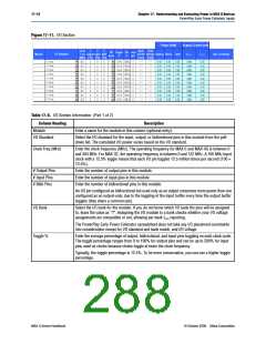
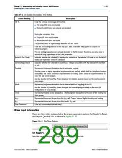
Each row in the I/O section represents a design module where the I/O pins have the
same frequency, toggle percentage, average capacitive load, I/O standard, and I/O
bank. Figure 17–11 shows the I/O section of the PowerPlay Early Power Estimator
spreadsheet and Table 17–6 describes the I/O module parameters.
© October 2008 Altera Corporation
MAX II Device Handbook

 ALTERA [ ALTERA CORPORATION ]