17–10
Chapter 17: Understanding and Evaluating Power in MAX II Devices
PowerPlay Early Power Estimator Inputs
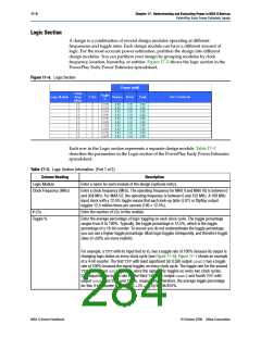
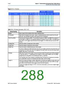
Figure 17–11. I/O Section
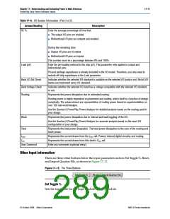
Table 17–6. I/O Section Information (Part 1 of 2)
Column Heading
Description
Module
Enter a name for the module in this column (optional entry).
I/O Standard
Select the I/O standard for the input, output, or bidirectional pins in this module from the pull-
down list. The calculated I/O power varies based on the I/O standard.
Clock Freq (MHz)
Enter the clock frequency (MHz). The operating frequency for MAX II and MAX IIG is between 0
and 304 MHz. For MAX IIZ, the operating frequency is between 0 and 152 MHz. A 100 MHz input
clock with a 12.5% toggle means that each I/O pin toggles 12.5 million times per second (100 ×
12.5%).
# Output Pins
# Input Pins
# Bidir Pins
Enter the number of output pins in this module.
Enter the number of input pins in this module.
Enter the number of bidirectional pins in this module.
An I/O pin configured as bidirectional but used only as an output consumes more power than one
configured as an output-only, due to the toggling of the input buffer every time the output buffer
toggles (they share a common pin).
I/O Bank
Toggle %
Select the I/O bank for the module. If you do not know which I/O bank the pins will be assigned
to, leave the value as “?”. Assigning the I/O module to a bank checks whether your I/O voltage
assignments are compatible or not, allowing per-bank ICCIO reporting.
The PowerPlay Early Power Estimator spreadsheet does not take any I/O placement constraints
into consideration except for I/O standard and bank match, and I/O voltage.
Enter the average percentage of output, bidirectional, and input pins toggling on each clock cycle.
The toggle percentage ranges from 0 to 100% for output pins and can be up to 200% for input
pins used as clocks because clocks toggle at twice the clock frequency.
Typically, the toggle percentage is 12.5%. To be more conservative, you can use a higher toggle
percentage.
MAX II Device Handbook
© October 2008 Altera Corporation

 ALTERA [ ALTERA CORPORATION ]