17–6
Chapter 17: Understanding and Evaluating Power in MAX II Devices
PowerPlay Early Power Estimator Inputs
Logic Section
A design is a combination of several design modules operating at different
frequencies and toggle rates. Each design module can have a different amount of
logic. For the most accurate power estimation, partition the design into different
design modules. You can partition your design by grouping modules by clock
frequency, location, hierarchy, or entities. Figure 17–5 shows the logic section in the
PowerPlay Early Power Estimator spreadsheet.
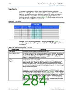
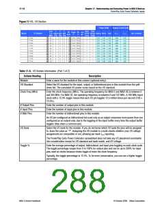
Figure 17–5. Logic Section
Each row in the Logic section represents a separate design module. Table 17–3
describes the parameters in the Logic section of the PowerPlay Early Power Estimator
spreadsheet.
Table 17–3. Logic Section Information (Part 1 of 2)
Column Heading
Logic Module
Description
Enter a name for each module of the design (optional entry).
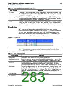
Clock Frequency (MHz)
Enter a clock frequency (MHz). The operating frequency for MAX II and MAX IIG is between 0
and 304 MHz. For MAX IIZ, the operating frequency is between 0 and 152 MHz. A 100 MHz
input clock with a 12.5% toggle means that each look-up table (LUT) or flipflop output
toggles 12.5 million times per second (100 × 12.5%).
# LEs
Enter the number of LEs in this module.
Toggle %
Enter the average percentage of logic toggling on each clock cycle. The toggle percentage
ranges from 0 to 100%. Typically, the toggle percentage is 12.5%, which is the toggle
percentage of a 16-bit counter. To ensure you do not underestimate the toggle percentage,
you can use a higher toggle percentage. Most logic toggles infrequently, and therefore toggle
rates of <50% are more realistic.
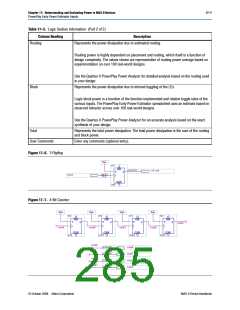
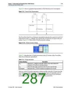
For example, a TFFwith its input tied to VCC has a toggle rate of 100% because its output is
changing logic states on every clock cycle (see Figure 17–6). Figure 17–7 shows an example
of a 4-bit counter. The first TFFwith least significant bit (LSB) output cout0has a toggle
rate of 100% because the signal toggles on every clock cycle. The toggle rate for the second
TFFwith output cout1is 50% since the signal only toggles on every two clock cycles.
Consequently, the toggle rate for the third TFFwith output cout2and fourth TFFwith
output cout3are 25% and 12.5%, respectively. Therefore, the average toggle percentage
for this 4-bit counter is (100 + 50 + 25 + 12.5)/4 = 46.875%.
MAX II Device Handbook
© October 2008 Altera Corporation

 ALTERA [ ALTERA CORPORATION ]