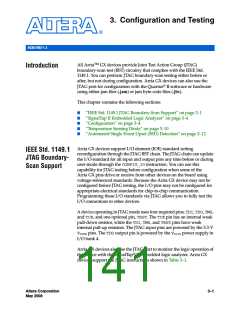
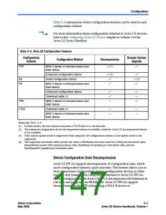
IEEE Std. 1149.1 JTAG Boundary-Scan Support
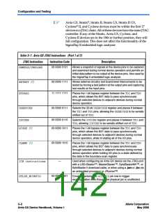
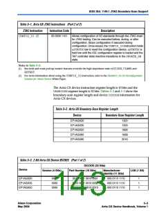
Table 3–1. Arria GX JTAG Instructions (Part 2 of 2)
JTAG Instruction
Instruction Code
Description
00 0000 1101
Allows configuration of I/O standards through the JTAG chain
for JTAG testing. Can be executed before, during, or after
configuration. Stops configuration if executed during
configuration. Once issued, the CONFIG_IOinstruction holds
nSTATUSlow to reset the configuration device. nSTATUSis
held low until the IOE configuration register is loaded and the
TAP controller state machine transitions to the UPDATE_DR
state.
CONFIG_IO (2)
Notes to Table 3–1:
(1) Bus hold and weak pull-up resistor features override the high-impedance state of HIGHZ, CLAMP, and
EXTEST.
(2) For more information about using the CONFIG_IOinstruction, refer to the MorphIO: An I/O Reconfiguration
Solution for Altera Devices White Paper.
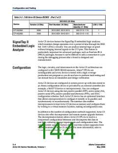
The Arria GX device instruction register length is 10 bits and the
USERCODEregister length is 32 bits. Tables 3–2 and 3–3 show the
boundary-scan register length and device IDCODEinformation for
Arria GX devices.
Table 3–2. Arria GX Boundary-Scan Register Length
Device
Boundary-Scan Register Length
EP1AGX20
EP1AGX35
EP1AGX50
EP1AGX60
EP1AGX90
1320
1320
1668
1668
2016
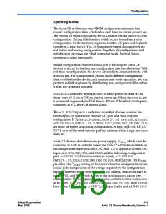
Table 3–3. 2-Bit Arria GX Device IDCODE (Part 1 of 2)
IDCODE (32 Bits)
Device
Version (4 Bits)
Part Number (16 Bits)
Manufacturer
LSB (1 Bit)
Identity (11 Bits)
EP1AGX20
EP1AGX35
EP1AGX50
0000
0000
0000
0010 0001 0010 0001
0010 0001 0010 0001
0010 0001 0010 0010
000 0110 1110
000 0110 1110
000 0110 1110
1
1
1
Altera Corporation
May 2008
3–3
Arria GX Device Handbook, Volume 1

 ALTERA [ ALTERA CORPORATION ]