A1180/81/82/83
Sensitive Two-Wire Field-Programmable Chopper-Stabilized Unipolar Hall Effect Switches
Application Information
For additional general application information, visit the Allegro
MicroSystems Web site at www. allegromicro.com.
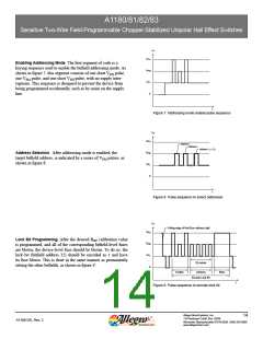
Typical Application Circuit
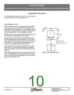
The A118x family of devices must be protected by an external
V+
bypass capacitor, CBYP, connected between the supply, VCC,
and the ground, GND, of the device. CBYP reduces both external
VCC
B
noise and the noise generated by the chopper-stabilization func-
tion. As shown in figure 3, a 0.01 μF capacitor is typical.
A118x
CBYP
Installation of CBYP must ensure that the traces that connect it to
the A118x pins are no greater than 5 mm in length.
0.01 uF
GND
GND
B
All high-frequency interferences conducted along the supply
lines are passed directly to the load through CBYP, and it serves
only to protect the A118x internal circuitry. As a result, the load
ECU (electronic control unit) must have sufficient protection,
other than CBYP, installed in parallel with the A118x.
A
A
B
Package UA Only
Maximum separation 5 mm
RSENSE
A series resistor on the supply side, RS (not shown), in combi-
nation with CBYP, creates a filter for EMI pulses. (Additional
information on EMC is provided on the Allegro MicroSystems
Web site.)
ECU
Figure 3. Typical application circuit
When determining the minimum VCC requirement of the A118x
device, the voltage drops across RS and the ECU sense resistor,
RSENSE, must be taken into consideration. The typical value for
RSENSE is approximately 100 Ω.
Allegro MicroSystems, Inc.
10
115 Northeast Cutoff, Box 15036
A1180-DS, Rev. 2
Worcester, Massachusetts 01615-0036 (508) 853-5000
www.allegromicro.com

 ALLEGRO [ ALLEGRO MICROSYSTEMS ]