A1180/81/82/83
Sensitive Two-Wire Field-Programmable Chopper-Stabilized Unipolar Hall Effect Switches
V+
V
PH
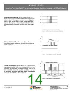
Enabling Addressing Mode. The first segment of code is a
keying sequence used to enable the bitfield addressing mode. As
shown in figure 7, this segment consists of one short VPH pulse,
one VPM pulse, and one short VPH pulse, with no supply inter-
ruptions. This sequence is designed to prevent the device from
being programmed accidentally, such as by noise on the supply
line.
V
PM
V
PL
0
t
Figure 7. Addressing mode enable pulse sequence
V+
V
V
PH
Address 1
Address 2
Address n ( ≤ 31)
Address Selection. After addressing mode is enabled, the
target bitfield address, is indicated by a series of VPM pulses, as
shown in figure 8.
PM
V
PL
0
t
Figure 8. Pulse sequence to select addresses
V+
Falling edge of final B address digit
OP
V
PH
Lock Bit Programming. After the desired BOP calibration value
is programmed, and all of the corresponding bitfield-level fuses
are blown, the device-level fuse should be blown. To do so, the
lock bit (bitfield address 32) should be encoded as 1 and have
its fuse blown. This is done in the same manner as permanently
setting the other bitfields, as shown in figure 9.
V
PM
V
PL
0
32 pulses
Enable
Address
Blow
Encode Lock Bit
t
Figure 9. Pulse sequence to encode lock bit
Allegro MicroSystems, Inc.
14
115 Northeast Cutoff, Box 15036
A1180-DS, Rev. 2
Worcester, Massachusetts 01615-0036 (508) 853-5000
www.allegromicro.com

 ALLEGRO [ ALLEGRO MICROSYSTEMS ]