A1180/81/82/83
Sensitive Two-Wire Field-Programmable Chopper-Stabilized Unipolar Hall Effect Switches
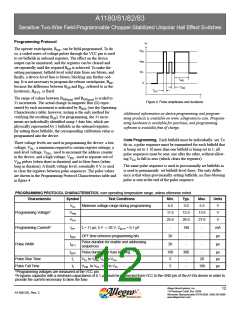
The pulse sequences consist of the following groups of pulses:
vertently setting the bitfield to 1. Instead, blowing the device-
level fuse protects the 0 bitfields from being accidentally set in
the future.
1. An enable sequence.
2. A bitfield address sequence.
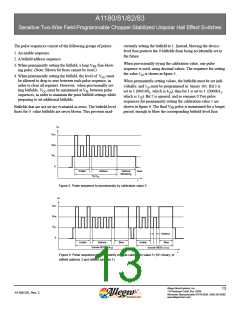
When provisionally trying the calibration value, one pulse
sequence is used, using decimal values. The sequence for setting
the value 510 is shown in figure 5.
3. When permanently setting the bitfield, a long VPH fuse-blow-
ing pulse. (Note: Blown bit fuses cannot be reset.)
4. When permanently setting the bitfield, the level of VCC must
be allowed to drop to zero between each pulse sequence, in
order to clear all registers. However, when provisionally set-
ting bitfields, VCC must be maintained at VPL between pulse
sequences, in order to maintain the prior bitfield settings while
preparing to set additional bitfields.
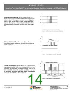
When permanently setting values, the bitfields must be set indi-
vidually, and 510 must be programmed as binary 101. Bit 3 is
set to 1 (0001002, which is 410), then bit 1 is set to 1 (0000012,
which is 110). Bit 2 is ignored, and so remains 0.Two pulse
sequences for permanently setting the calibration value 5 are
shown in figure 6. The final VPH pulse is maintained for a longer
period, enough to blow the corresponding bitfield-level fuse.
Bitfields that are not set are evaluated as zeros. The bitfield-level
fuses for 0 value bitfields are never blown. This prevents inad-
V+
V
PH
V
PM
V
PL
0
Enable
Address
Clear
t
Optional
Monitoring
Try 5
10
Figure 5. Pulse sequence to provisionally try calibration value 5.
V+
V
PH
V
PM
V
PL
0
Address
Blow
Enable
Address
Blow
Enable
Encode 00100 (4
2
)
Encode 00001 (1
10
)
10
2
t
Figure 6. Pulse sequence to permanently encode calibration value 5 (101 binary, or
bitfield address 3 and bitfield address 1).
Allegro MicroSystems, Inc.
13
115 Northeast Cutoff, Box 15036
A1180-DS, Rev. 2
Worcester, Massachusetts 01615-0036 (508) 853-5000
www.allegromicro.com

 ALLEGRO [ ALLEGRO MICROSYSTEMS ]