A1180/81/82/83
Sensitive Two-Wire Field-Programmable Chopper-Stabilized Unipolar Hall Effect Switches
Programming Protocol
V+
The operate switchpoint, BOP, can be field-programmed. To do
V
PH
so, a coded series of voltage pulses through the VCC pin is used
to set bitfields in onboard registers. The effect on the device
output can be monitored, and the registers can be cleared and
set repeatedly until the required BOP is achieved. To make the
setting permanent, bitfield-level solid state fuses are blown, and
finally, a device-level fuse is blown, blocking any further cod-
V
PM
V
PL
0
T
d(P)
ing. It is not necessary to program the release switchpoint, BRP
because the difference between BOP and BRP, referred to as the
hysteresis, BHYS, is fixed.
,
T
d(0)
T
d(1)
t
The range of values between BOP(min) and BOP(max) is scaled to
31 increments. The actual change in magnetic flux (G) repre-
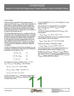
Figure 4. Pulse amplitudes and durations
sented by each increment is indicated by BRES (see the Operating
Characteristics table; however, testing is the only method for
verifying the resulting BOP). For programming, the 31 incre-
ments are individually identified using 5 data bits, which are
physically represented by 5 bitfields in the onboard registers.
By setting these bitfields, the corresponding calibration value is
programmed into the device.
Additional information on device programming and program-
ming products is available on www. allegromicro.com. Program-
ming hardware is available for purchase, and programming
software is available free of charge.
Code Programming. Each bitfield must be individually set. To
do so, a pulse sequence must be transmitted for each bitfield that
is being set to 1. If more than one bitfield is being set to 1, all
pulse sequences must be sent, one after the other, without allow-
ing VCC to fall to zero (which clears the registers).
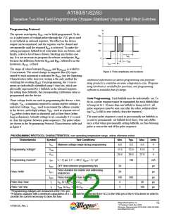
Three voltage levels are used in programming the device: a low
voltage, VPL , a minimum required to sustain register settings; a
mid-level voltage, VPM , used to increment the address counter
in the device; and a high voltage, VPH , used to separate sets of
VPM pulses (when short in duration) and to blow fuses (when
long in duration). A fourth voltage level, essentially 0 V, is used
to clear the registers between pulse sequences. The pulse values
are shown in the Programming Protocol Characteristics table and
in figure 4.
The same pulse sequence is used to provisionally set bitfields as
is used to permanently set bitfield-level fuses. The only differ-
ence is that when provisionally setting bitfields, no fuse-blowing
pulse is sent at the end of the pulse sequence.
PROGRAMMING PROTOCOL CHARACTERISTICS, over operating temperature range, unless otherwise noted
Characteristic
Symbol
VPL
Test Conditions
Min.
4.5
Typ.
5.0
Max.
5.5
Units
Minimum voltage range during programming
V
V
V
Programming Voltage1
VPM
11.5
25.0
12.5
26.0
13.5
27.0
VPH
Programming Current2
Pulse Width
IPP
td(0)
td(1)
tr = 11 μs; 5 V → 26 V; CBYP = 0.1 μF
-
190
-
-
-
mA
μs
OFF time between programming bits
20
20
-
-
Pulse duration for enable and addressing
sequences
μs
td(P)
tr
Pulse duration for fuse blowing
VPL to VPM; VPL to VPH
100
5
300
-
μs
μs
μs
Pulse Rise Time
Pulse Fall Time
-
-
20
tf
VPM to VPL; VPH to VPL
5
100
1Programming voltages are measured at the VCC pin.
2A bypass capacitor with a minimum capacitance of 0.1 μF must be connected from VCC to the GND pin of the A118x device in order to
provide the current necessary to blow the fuse.
Allegro MicroSystems, Inc.
12
115 Northeast Cutoff, Box 15036
A1180-DS, Rev. 2
Worcester, Massachusetts 01615-0036 (508) 853-5000
www.allegromicro.com

 ALLEGRO [ ALLEGRO MICROSYSTEMS ]