[ASAHI KASEI]
[AK7740ET]
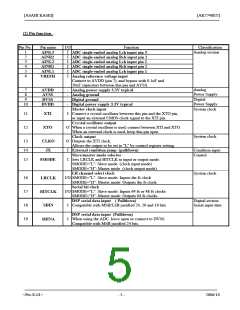
Pin No.
Pin name
I/O
O
Function
Classification
Digital section
20
SDOUTA
DSP serial data output
Outputs MSB justified 24-bit data selected from ADC or SDOUTD1 Serial output data
by control register setting
21
22
O
O
SDOUT
DRDY
DSP serial data output
Outputs MSB justified 24-bit data
Output data ready pin for microcontroller interface
Microcontroller
interface
Power supply
23
24
25
26
-
-
O
O
DVSS
DVDD
RDY
SO
Digital ground
Digital power supply 3.3V typical
Microcontroller
interface
Data write ready output for microcontroller interface
Serial data output for microcontroller interfaces
Microcontroller interface serial data input and serial data
output control
When SI does not use, leave SI=”L”
Microcontroller interface serial data clock
27
I
SI
28
I When SCLK is not used, leave SCLK=”H”
SCLK
RQ
Microcontroller interface writes request pin.
29
30
31
I
RQ =”L”: Microcontroller interface enable
I
I
Reset
System Reset
S_RESET
Reset (for initialization)
INIT_RESET
Input “L” to initialize the AK7740 at power-on
Digital power supply 3.3V typical
Digital ground
Substrate ground
DAC2 Rch analog output
DAC2 Lch analog output
DAC1 Rch analog output
DAC1 Lch analog output
Analog power supply 3.3V typical
Common voltage
Connect to 0.1uF and 10uF capacitors between this pin and
AVSS. Do not connect to external circuitry
An alog ground
ADC Rch analog inverted input
ADC Rch analog non-inverted input
ADC Lch analog inverted input
ADC Lch analog non-inverted input
ADC single-ended analog Rch input 4
ADC single-ended analog Lch input 4
ADC single-ended analog Rch input 3
32
33
34
35
36
37
38
39
40
-
-
-
Power supply
DVDD
DVSS
BVSS
AOUTR2
AOUTL2
AOUTR1
AOUTL1
AVDD
Power supply
Analog section
O
O
O
O
-
Power supply
Analog section
O
VCOM
41
42
43
44
45
46
47
48
-
I
I
I
I
I
I
I
Power supply
Analog section
AVSS
AINR-
AINR+
AINL-
AINL+
AINR4
AINL4
AINR3
<Pre-E-01>
- 6 -
2006/10

 AKM [ ASAHI KASEI MICROSYSTEMS ]