[ASAHI KASEI]
[AK7740ET]
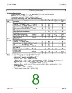
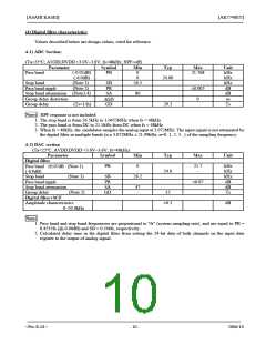
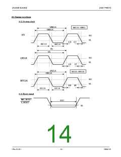
(4) Digital filter characteristics
Values described below are design values, cited for reference.
4-1) ADC Section:
(Ta=25°C; AVDD,DVDD =3.0V~3.6V; fs=48kHz; HPF=off)
Parameter
Symbol
Min
0
Typ
Max
21.768
Unit
kHz
kHz
kHz
dB
Pass band
Stop band
(-0.02dB)
(-6.0dB)
(Note 1)
(Note 2)
PB
0
24.00
SB
PR
SA
26.5
Pass band ripple
±0.005
0
Stop band attenuation (Note3,4)
Group delay distortion
80
dB
us
Ts
∆GD
GD
Group delay
(Ts=1/fs)
29.3
Note: : HPF response is not included
1. The stop band is from 26.5kHz to 3.0455MHz when fs = 48kHz.
2. The pass band is from DC to 21.5kHz from DC when fs = 48kHz.
3. When fs = 48kHz, the modulator samples the analog input at 3.072MHz. The input signal is not attenuated by
the digital filter in multiple bands (n x 3.072MHz ± 21.99kHz; n=0, 1, 2, 3...) of the sampling frequency.
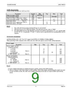
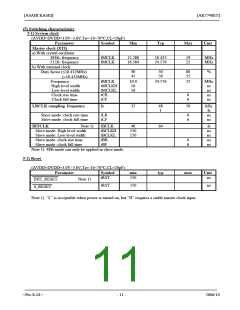
4-2) DAC section
(Ta=25°C; AVDD,DVDD =3.0V~3.6V; fs=48kHz)
Parameter
Digital filter
Symbol
Min
Typ
Max
Unit
PB
0
-
21.7
-
kHz
kHz
kHz
dB
dB
Ts
Pass band ±0.07dB (Note 1)
24.0
(-6.0dB)
Stop band
(Note 1)
SB
PR
SA
GD
26.2
Pass band ripple
Stop band attenuation
Group delay
±0.07
47
-
(Note 2)
15
Digital filter+SCF
Amplitude characteristics
±0.5
dB
0~20.0kHz
Note:
1. Pass band and stop band frequencies are proportional to "fs" (system sampling rate), and are equal to PB =
0.4535fs (@-0.06dB) and SB = 0.546fs, respectively.
2. Calculated delay time in the digital filter from setting the 24-bit data of both channels on the input data
register to the output of analog signal.
<Pre-E-01>
- 10 -
2006/10

 AKM [ ASAHI KASEI MICROSYSTEMS ]