ASAHI KASEI
[AK5385B]
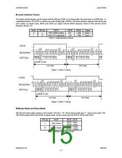
Audio Interface Format
Two kinds of data formats can be chosen with the DIF pin (Table 4). In both modes, the serial data is in MSB first, 2’s
complement format. The SDTO is clocked out on the falling edge of BICK. The audio interface supports both master and
slave modes. In master mode, BICK and LRCK are output with the BICK frequency fixed to 64fs and the LRCK
frequency fixed to 1fs.
Mode
0
1
DIF pin
SDTO
24bit, MSB justified
24bit, I2S Compatible
LRCK
H/L
L/H
BICK
≥ 48fs
≥ 48fs
Figure
Figure 1
Figure 2
L
H
Table 4. Audio Interface Format
LRCK
0 1
2
20 21 22 23 24
31 0 1 2
23 22
20 21 22 23 24
4 3 2 1 0
31 0 1
BICK(64fs)
SDTO(o)
23 22
4 3 2
1
0
23
23:MSB, 0:LSB
Lch Data
Rch Data
Figure 1. Mode 0 Timing
LRCK
0
1
2
3
21 22 23 24 25
0
1
2
21 22 23 24 25
0 1
BICK(64fs)
SDTO(o)
23 22
4
3
2
1
0
23 22
4 3 2 1 0
23:MSB, 0:LSB
Lch Data
Figure 2. Mode 1 Timing
Rch Data
Master Mode and Slave Mode
The M/S pin selects either master or slave modes. M/S pin = “H” selects master mode and “L” selects slave mode. The
AK5385B outputs BICK and LRCK in master mode. In slave mode, provide MCLK, BICK and LRCK.
M/S pin
L
Mode
BICK, LRCK
BICK = Input
LRCK = Input
BICK = Output
LRCK = Output
Slave Mode
H
Master Mode
Table 5. Master mode/Slave mode
MS0406-E-00
2005/08
- 15 -

 AKM [ ASAHI KASEI MICROSYSTEMS ]