ASAHI KASEI
[AK5385B]
OPERATION OVERVIEW
System Clock
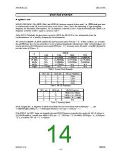
MCLK (256fs/384fs/512fs), BICK (48fs∼) and LRCK (fs) clocks are required in slave mode. The LRCK clock input must
be synchronized with MCLK, however the phase is not critical. Table 1 shows the relationship of typical sampling
frequency and the system clock frequency. MCLK frequency is selected by CKS1-0 pins as shown in Table 2 and LRCK
frequency is selected by DFS1-0 pins as shown in Table 3.
As the AK5385B includes the phase detect circuit for LRCK, the AK5385B is reset automatically when the
synchronization is out of phase by changing the clock frequencies.
All external clocks (MCLK, BICK and LRCK) must be present unless PDN pin = “L”. If these clocks are not provided,
the AK5385B may draw excess current due to its use of internal dynamically refreshed logic. If the external clocks are not
present, place the AK5385B in power-down mode (PDN pin = “L”). In master mode, the master clock (MCLK) must be
provided unless PDN pin = “L”.
MCLK
fs
128fs
N/A
N/A
N/A
N/A
256fs
8.192MHz
11.2896MHz
12.288MHz
24.576MHz
N/A
384fs
12.288MHz
16.9344MHz
18.432MHz
N/A
512fs
16.384MHz
22.5792MHz
24.576MHz
N/A
32kHz
44.1kHz
48kHz
96kHz
192kHz
24.576MHz
N/A
N/A
Table 1. System Clock Example
CKS1 pin
CKS0 pin
MCLK Frequency
L
L
H
H
L
H
L
H
256fs
128fs
512fs
384fs
Table 2. MCLK Frequency
DFS1 pin
DFS0 pin
LRCK Frequency
L
L
H
H
L
H
L
8kHz ≤ fs ≤ 54kHz
54kHz < fs ≤ 108kHz
108kHz < fs ≤ 216kHz
N/A
H
Table 3. Sampling Speed
When changing MCLK frequency in master/slave mode, the AK5385B should reset by PDN pin = “L”. (ex.
12.288MHz(@fs=48kHz) to 24.576MHz(@fs=96kHz) at CKS1 pin = CKS0 pin = “L”.
If the CKS1-0 and DFS1-0 pins are changed with same MCLK frequency in master/slave mode (ex. MCLK is fixed to
24.576MHz and fs is changed from 48kHz (CKS1 pin = “L”, CKS0 pin = “L”) to 96kHz (CKS1 pin = “L”, CKS0 pin =
“H”)), no reset by PDN pin = “L” is required.
MS0406-E-00
2005/08
- 14 -

 AKM [ ASAHI KASEI MICROSYSTEMS ]