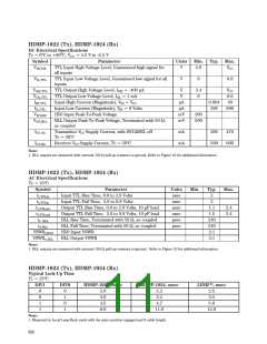
HDMP-1022 (Tx), HDMP-1024 (Rx)
DC Electrical Specifications
Tc = 0°C to +85°C, VCC = 4.5 V to -5.5 V
Symbol
Parameter
Units
Min. Typ. Max.
VIH,TTL
TTL Input High Voltage Level, Guaranteed high signal for
all inputs
V
2.0
VCC
VIL,TTL
TTL Input Low Voltage Level, Guaranteed low signal for all
inputs
V
0
0.8
VOH,TTL
VOL,TTL
IIH,TTL
IIL,TTL
VIP,H50
VOP,BLL
TTL Output High Voltage Level, IOH = -400 µA
TTL Output Low Voltage Level, IOL = 1 mA
V
V
µA
µA
mV
mV
2.4
0
VCC
0.6
40
Input High Current (Magnitude), V = VCC
0.004
295
IN
Input Low Current (Magnitude), VIN = 0 Volts
H50 Input Peak-To-Peak Voltage
BLL Output Peak-To-Peak Voltage, Terminated with 50 Ω,
600
200
500
ac coupled
ICC,Tx
ICC,Rx
Transmitter VCC Supply Current, with HCLKSEL off
Tc = 50°C
Receiver VCC Supply Current, Tc = 50°C
mA
mA
385
500
470
600
Note:
1. BLL outputs are measured with external 150 Ω pull-up resistors to ground. Refer to Figure 23 for additional information.
HDMP-1022 (Tx), HDMP-1024 (Rx)
AC Electrical Specifications
Tc = 25°C
Symbol
tr,TTLin
tf,TTLin
tr,TTLout
tf,TTLout
tr, BLL
tf,BLL
VSWRi,H50
VSWRo,BLL
Parameter
Units
nsec
nsec
nsec
nsec
psec
psec
Min.
Typ.
2
2
1.1
1.5
240
240
2:1
2:1
Max.
Input TTL Rise Time, 0.8 to 2.0 Volts
Input TTL Fall Time, 2.0 to 0.8 Volts
Output TTL Rise Time, 0.8 to 2.0 Volts, 10 pF load
Output TTL Fall Time, 2.0 to 0.8 Volts, 10 pF load
BLL Rise Time, Terminated with 50 Ω, ac coupled
BLL Fall Time, Terminated with 50 Ω, ac coupled
H50 Input VSWR
2.4
2.4
BLL Output VSWR
Note:
1. BLL outputs are measured with external 150 Ω pull-up resistors to ground. Refer to Figure 23 for additional information.
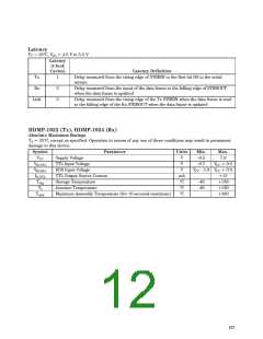
HDMP-1022 (Tx), HDMP-1024 (Rx)
Typical Lock-Up Time
Tc = 25°C
DIV1
DIV0
HDMP-1022, msec
HDMP-1024, msec
LINK[1], msec
0
0
1
1
0
1
0
1
2.0
3.0
4.5
8.0
2.2
3.2
4.7
2.5
3.5
5.0
11.0
12.0
Note:
1. Measured in Local Loop-Back mode with the state machine engaged and 0 cable length.
626

 AGILENT [ AGILENT TECHNOLOGIES, LTD. ]