DIN
LIN
INPUT
SELECT
INPUT
SAMPLER
D-FIELD
DECODER
FRAME
DEMUX
D0..D19
FLAG
DAV*
CAV*
FF
INTERNAL
CLOCKS
PHASE /
FREQ
DETECT
C-FIELD
DECODER
FDIS
PH1
ERROR
CLOCK
GENERATOR
CAP0
0.1 µF
CAP1
FLAGSEL
FILTER
LINKRDY
STAT1
STATE
MACHINE
STAT0
CLOCK
SELECT
VCO
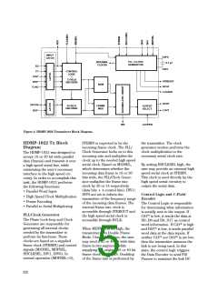
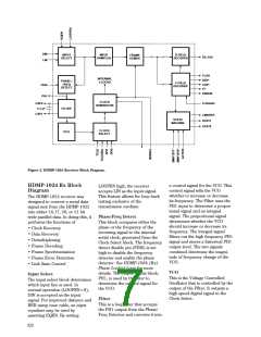
Figure 5. HDMP-1024 Receiver Block Diagram.
HDMP-1024 Rx Block
Diagram
a control signal for the VCO. This
control signal tells the VCO
whether to increase or decrease
its frequency. The Filter uses the
PH1 input to determine a propor-
tional signal and an integral
signal. The proportional signal
determines whether the VCO
should increase or decrease its
frequency. The integral signal
filters out the high frequency PH1
signal and stores a historical PH1
output level. The two signals
combined determine the magni-
tude of frequency change of the
VCO.
LOOPEN high, the receiver
accepts LIN as the input signal.
This feature allows for loop back
testing exclusive of the
The HDMP-1024 receiver was
designed to convert a serial data
signal sent from the HDMP-1022
into either 16,17, 20, or 21 bit
wide parallel data. In doing this, it
performs the functions of
• Clock Recovery
• Data Recovery
• Demultiplexing
• Frame Decoding
• Frame Synchronization
• Frame Error Detection
• Link State Control
transmission medium.
Phase/Freq Detect
This block compares either the
phase or the frequency of the
incoming signal to the internal
serial clock, generated from the
Clock Select block. The frequency
detect disable pin (FDIS) is set
high to disable the frequency
detector and enable the phase
detector. See HDMP-1024 (Rx)
Phase Locked Loop for more
details. The output of this block,
PH1, is used by the filter to
determine the control signal for
the VCO.
VCO
Input Select
This is the Voltage Controlled
Oscillator that is controlled by the
output of the Filter. It outputs a
high speed digital signal to the
Clock Select.
The input select block determines
which input line is used. In
normal operation (LOOPEN=0),
DIN is accepted as the input
signal. For improved distance and
BER using coax cable, an input
equalizer may be used by
Filter
This is a loop filter that accepts
the PH1 output from the Phase/
Freq Detector and converts it into
asserting EQEN. By setting
622

 AGILENT [ AGILENT TECHNOLOGIES, LTD. ]