4
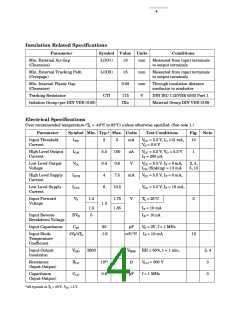
Insulation Related Specifications
Parameter
Symbol Value Units
Conditions
Min. External Air Gap
(Clearance)
L(IO1)
≥5
mm
mm
mm
V
Measured from input terminals
to output terminals
Min. External Tracking Path
(Creepage)
L(IO2)
≥5
Measured from input terminals
to output terminals
Min. Internal Plastic Gap
(Clearance)
0.08
Through insulation distance
conductor to conductor
Tracking Resistance
CTI
175
IIIa
DIN IEC 112/VDE 0303 Part 1
Material Group DIN VDE 0109
Isolation Group (per DIN VDE 0109)
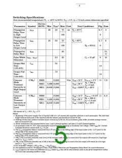
Electrical Specifications
Over recommended temperature (T = -40°C to 85°C) unless otherwise specified. (See note 1.)
A
Parameter
Symbol Min. Typ.* Max. Units
Test Conditions
Fig. Note
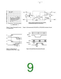
Input Threshold
Current
ITH
IOH
VOL
ICCH
ICCL
VF
2
5.5
0.4
4
5
mA
µA
V
VCC = 5.5 V, IO ≥13 mA,
VO = 0.6 V
13
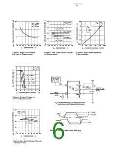
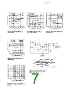
High Level Output
Current
100
0.6
VCC = 5.5 V, VO = 5.5 V
IF = 250 µA
1
Low Level Output
Voltage
VCC = 5.5 V, IF = 5 mA,
IOL (Sinking) = 13 mA
2, 4,
5, 13
High Level Supply
Current
7.5
mA
VCC = 5.5 V, IF = 0 mA,
Low Level Supply
Current
6
10.5
VCC = 5.5 V, IF = 10 mA,
Input Forward
Voltage
1.4
1.75
1.85
V
T = 25°C
A
3
1.5
1.3
5
IF = 10 mA
Input Reverse
BVR
IR = 10 µA
Breakdown Voltage
Input Capacitance
CIN
60
pF
VF = 0V, f = 1 MHz
Input Diode
Temperature
Coefficient
∆VF/∆TA
-1.6
mV/°C IF = 10 mA
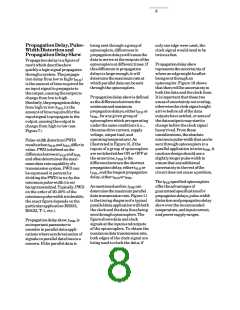
12
Input-Output
Insulation
V
2500
VRMS
Ω
RH ≤ 50%, t = 1 min.
3, 4
3
ISO
Resistance
(Input-Output)
RI-O
CI-O
1012
0.6
VI-O = 500 V
f = 1 MHz
Capacitance
pF
3
(Input-Output)
*All typicals at T = 25°C, VCC = 5 V.
A

 AGILENT [ AGILENT TECHNOLOGIES, LTD. ]