3
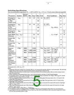
RecommendedOperatingConditions
Parameter
Symbol
IFL*
Min.
0
Max.
250
15
Units
µA
InputCurrent,LowLevel
InputCurrent,HighLevel
SupplyVoltage,Output
Fan Out (RL = 1 kΩ)
IFH
5
mA
V
V
CC
4.5
5.5
5
N
TTL
Loads
OutputPull-UpResistor
OperatingTemperature
RL
330
-40
4,000
85
Ω
T
A
°C
* The off condition can also be guaranteed by ensuring that VF(off) ≤0.8 volts.
AbsoluteMaximumRatings
(NoDeratingRequiredupto85°C)
StorageTemperature .................................................... -55°C to +125°C
OperatingTemperature .................................................. -40°C to +85°C
ForwardInputCurrent-IF (seeNote2) ....................................... 20mA
ReverseInputVoltage-VR ................................................................. 5 V
SupplyVoltage-VCC (1MinuteMaximum) ........................................ 7 V
OutputCollectorCurrent-IO........................................................ 50mA
OutputCollectorPowerDissipation ............................................ 85 mW
OutputCollectorVoltage-VO ............................................................ 7 V
(Selectionforhigheroutputvoltagesupto20Visavailable)
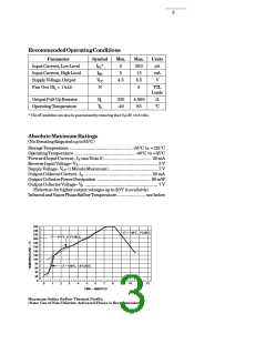
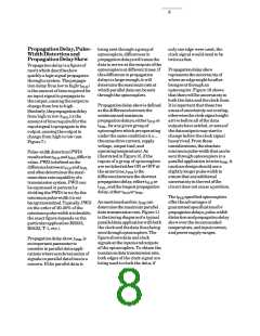
InfraredandVaporPhaseReflowTemperature ....................... see below
260
240
∆T = 145°C, 1°C/SEC
220
∆T = 115°C, 0.3°C/SEC
200
180
160
140
120
100
80
∆T = 100°C, 1.5°C/SEC
60
40
20
0
0
1
2
3
4
5
6
7
8
9
10
11
12
TIME – MINUTES
Maximum Solder Reflow Thermal Profile.
(Note: Use of Non-Chlorine Activated Fluxes is Recommended.)

 AGILENT [ AGILENT TECHNOLOGIES, LTD. ]