2
TheHCPL-M600/01/11are
suitableforhighspeedlogic
interfacing,input/output
buffering,aslinereceiversin
environmentsthatconventional
linereceiverscannottolerate,and
arerecommendedforusein
extremelyhighgroundorinduced
noiseenvironments.
Applications
•IsolatedLineReceiver
•Simplex/MultiplexData
Transmission
•Computer-Peripheral
Interface
•MicroprocessorSystem
Interface
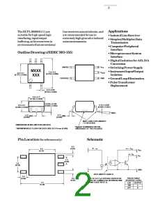
OutlineDrawing(JEDECMO-155)
•DigitalIsolationforA/D,D/A
Conversion
•SwitchingPowerSupply
•InstrumentInput/Output
Isolation
•GroundLoopElimination
ANODE
1
3
6
5
V
V
CC
MXXX
XXX
7.0 ± 0.2
(0.276 ± 0.008)
4.4 ± 0.1
(0.173 ± 0.004)
OUT
CATHODE
4
GND
•PulseTransformer
Replacement
0.4 ± 0.05
(0.016 ± 0.002)
3.6 ± 0.1*
(0.142 ± 0.004)
0.102 ± 0.102
(0.004 ± 0.004)
0.15 ± 0.025
(0.006 ± 0.001)
2.5 ± 0.1
(0.098 ± 0.004)
7° MAX.
1.27
(0.050)
0.71
BSG
MIN.
(0.028)
MAX. LEAD COPLANARITY
= 0.102 (0.004)
DIMENSIONS IN MILLIMETERS (INCHES)
"Agilent" IS MARKED ON THE
UNDERSIDE OF THE PACKAGE
* MAXIMUM MOLD FLASH ON EACH SIDE IS 0.15 mm (0.006)
PinLocation(forreferenceonly)
Schematic
0.3
(0.01)
I
+
1
I
CC
F
4.4
(0.17)
V
V
CC
O
6
5
I
O
1.3
(0.05)
2.5
(0.10)
–
3
GND
4
HCPL-M601/11 SHIELD
0.9
(0.04)
TRUTH TABLE
(POSITIVE LOGIC)
0.5
(0.02)
USE OF A 0.1 µF BYPASS CAPACITOR
MUST BE CONNECTED BETWEEN PINS
6 AND 4 (SEE NOTE 1).
7.2
(0.28)
LED
ON
OUTPUT
L
OFF
H

 AGILENT [ AGILENT TECHNOLOGIES, LTD. ]