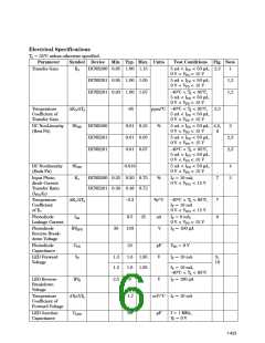
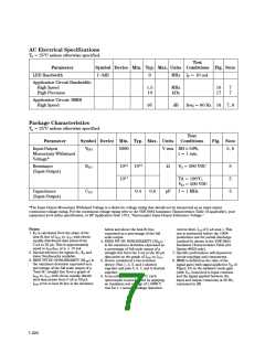
AC Electrical Specifications
TA = 25°C unless otherwise specified.
Test
Symbol Device Min. Typ. Max. Units Conditions Fig. Note
Parameter
LED Bandwidth
f -3dB
9
MHz IF = 10 mA
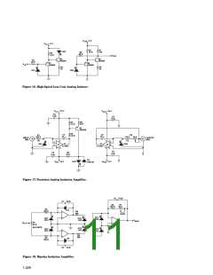
Application Circuit Bandwidth:
High Speed
1.5
10
MHz
kHz
16
17
7
7
High Precision
Application Circuit: IMRR
High Speed
95
dB
freq = 60 Hz 16 7, 8
Package Characteristics
TA = 25°C unless otherwise specified.
Test
Parameter
Input-Output
Symbol Device Min. Typ. Max. Units
Conditions
Fig. Note
V
5000
V rms RH ≤ 50%,
5, 6
ISO
Momentary-Withstand
Voltage*
t = 1 min.
Resistance
(Input-Output)
RI-O
1012 1013
1011
Ω
VO = 500 VDC
5
5
5
TA = 100°C,
V = 500 VDC
IO
Capacitance
CI-O
0.4
0.6
pF
f = 1 MHz
(Input-Output)
*The Input-Output Momentary Withstand Voltage is a dielectric voltage rating that should not be interpreted as an input-output
continuous voltage rating. For the continuous voltage rating refer to the VDE 0884 Insulation Characteristics Table (if applicable), your
equipment level safety specification, or HP Application Note 1074, “Optocoupler Input-Output Endurance Voltage.”
Notes:
below and above the best fit line,
expressed as a percentage of the full
scale output.
current limit, II-O of 5 µA max.). This
test is performed before the 100%
production test for partial discharge
(method b) shown in the VDE 0884
Insulation Characteristics Table (for
Option #050 only).
7. Specific performance will depend on
circuit topology and components.
8. IMRR is defined as the ratio of the
signal gain (with signal applied to VIN of
Figure 16) to the isolation mode gain
(with VIN connected to input common
and the signal applied between the
input and output commons) at 60 Hz,
expressed in dB.
1. K3 is calculated from the slope of the
best fit line of IPD2 vs. IPD1 with eleven
equally distributed data points from
5 nA to 50 µA. This is approximately
equal to IPD2/IPD1 at IF = 10 mA.
4. ENDS FIT DC NONLINEARITY (NLEF
)
is the maximum deviation expressed as
a percentage of full scale output of a
straight line from the 5 nA to the 50 µA
data point on the graph of IPD2 vs. IPD1
5. Device considered a two-terminal
device: Pins 1, 2, 3, and 4 shorted
together and pins 5, 6, 7, and 8 shorted
together.
6. In accordance with UL 1577, each
optocoupler is proof tested by applying
an insulation test voltage of ≥ 6000 V
rms for ≥ 1 second (leakage detection
2. Special selection for tighter K1, K3 and
lower Nonlinearity available.
.
3. BEST FIT DC NONLINEARITY (NLBF) is
the maximum deviation expressed as a
percentage of the full scale output of a
“best fit” straight line from a graph of
IPD2 vs. IPD1 with eleven equally distrib-
uted data points from 5 nA to 50 µA.
IPD2 error to best fit line is the deviation
1-424

 AGILENT [ AGILENT TECHNOLOGIES, LTD. ]