PCB Assembly Considerations
shoulders do not normally
rest on the PCB surface.
The fixture should be
designed to expose the
sensor leads to solder while
shielding the optical
Recommend to hold the PCB
first vertically for the
kapton removal process.
1. Insert the sensor and all
other electrical components
into PCB.
7. Insert PCB assembly over
the lens onto the base plate
aligning post to retain PCB
assembly. The sensor
2. Insert the LED into the
assembly clip and bend the
leads 90 degrees.
aperture from direct solder
contact.
aperture ring should self-
align to the lens.
3. Insert the LED/clip
assembly into PCB.
5. Place the lens onto the base
plate.
8. The optical position
4. Wave Solder the entire
assembly in a no-wash
solder process utilizing
solder fixture. The solder
fixture is needed to protect
the sensor during the solder
process. It also sets the
correct sensor-to-PCB
6. Remove the protective
kapton tape from optical
aperture of the sensor. Care
must be taken to keep
reference for the PCB is set
by the base plate and lens.
Note that the PCB motion
due to button presses must
be minimized to maintain
optical alignment.
contaminants from entering
the aperture. Recommend
not to place the PCB facing
up during the entire mouse
assembly process.
9. Install mouse top case.
There MUST be a feature in
the top case to press down
onto the clip to ensure all
components are interlocked
to the correct vertical
height.
distance as the lead
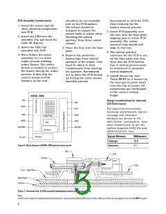
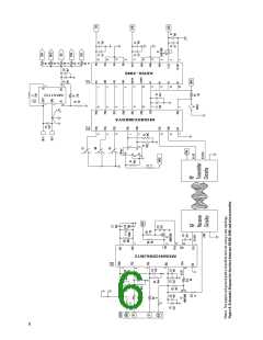
ADNS-3040
VDD
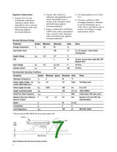
Design considerations for improved
ESD Performance
NCS
AVDD
SCLK
For improved electrostatic
discharge performance, typical
creepage and clearance
GND
MOSI
Image Array
distance are shown in the
table below. Assumption: base
plate construction as per the
Agilent supplied IGES file and
ADNS-3120-001 lens.
AGND
MISO
DSP
SHTDWN
MOTION
Oscillator
Typical Distance
Creepage
Millimeters
16.0
LED Drive
XY_LED
Figure 6. Block diagram of ADNS-3040 optical mouse sensor
Clearance
2.1
Clip
LED
Sensor
PCB
Lens / Light Pipe
Base Plate
Surface
Figure 7. Sectional view of PCB assembly highlighting optical mouse components
Note
that the lens material is polycarbonate and therefore, cyanoacrylate based adhesives or other adhesives that may damage the lens should NOT be used.
5

 AGILENT [ AGILENT TECHNOLOGIES, LTD. ]