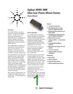
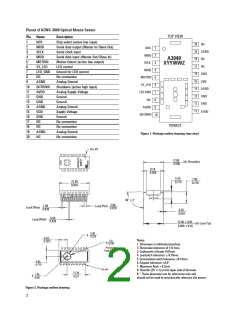
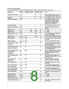
Pinout of ADNS-3040 Optical Mouse Sensor
TOP VIEW
Pin
1
Name
NCS
Description
Chip select (active low input)
Serial data output (Master In/Slave Out)
Serial clock input
Serial data input (Master Out/Slave In)
Motion Detect (active low output)
LED control
20
NC
2
MISO
SCLK
MOSI
MOTION
XY_LED
LED_GND
NC
1
2
NCS
19 AGND
3
MISO
SCLK
4
A3040
NC
18
5
3
XYYWWZ
17
16 GND
NC
6
MOSI
MOTION
XY_LED
4
7
Ground for LED current
No connection
8
5
15
14
VDD
9
AGND
SHTDWN
AVDD
GND
Analog Ground
6
10
11
12
13
14
15
16
17
18
19
20
Shutdown (active high input)
Analog Supply Voltage
Ground
AGND
LED GND
7
13 GND
8
NC
GND
Ground
GND
12
11
AGND
VDD
Analog Ground
AGND
9
AVDD
Supply Voltage
SHTDWN
10
GND
Ground
NC
No connection
PINOUT
NC
No connection
AGND
NC
Analog Ground
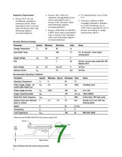
Figure 1. Package outline drawing (top view)
No connection
Pin #1
12.85
0.506
(At Shoulder)
9.10
0.358
5.43
0.214
7.05
0.278
22.30
0.878
90˚ 3˚
2.00
0.079
1.00
0.039
Lead Pitch
Lead Offset
0.25
0.010
0.50
0.020
Lead Width
12.85 0.65
0.506 0.26
(At Lead Tip)
5.60
0.220
φ
6.025
0.2372
Notes:
5.0
0.197
φ
1. Dimension in millimeters(inches).
2. Dimension tolerence of 0.1mm.
3. Coplanarity of leads: 0.01mm.
4. Lead pitch toleronce: 0.15mm.
5. Cummulative pitch tolerance: 0.15mm.
6. Angular tolerance: 3.0˚.
Protective
Kapton Tape
4.55
0.179
7. Maximum flash + 0.2mm
Pin #1
8. Chamfer (25˚ x 2) on the taper side of the lead.
9. * These dimension are for references only and
should not be used to mechanically reference the sensor.
13.38
0.527
1.05
0.041
φ
Figure 2. Package outline drawing
2

 AGILENT [ AGILENT TECHNOLOGIES, LTD. ]