Ambassador T8100A, T8102, and T8105
H.100/H.110 Interfaces and Time-Slot Interchangers
Advance Data Sheet
November 1999
If the user wishes to poll the CAM for its contents, then
the RDCn or read CAM (upper/lower) command can be
used to query a particular location (AMR bit 5: when 1,
equals 0—255, when 0, equals 256—511 [T8102,
T8105 only]) in a specific block using the LAR for the
location address. The contents of the CAM and tag
location are transferred to the holding registers, and
then the time slot, stream plus control, and tag are
returned (in sequence) from four consecutive IDR
reads (see Section 3.4.2 Setting Up H-Bus Connec-
tions on page 75 for more details). The MSB of the time
slot is the validity bit. The actual RDCn operation is
one-cycle.
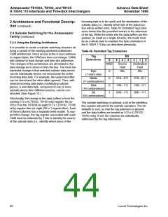
2 Architecture and Functional Descrip-
tion (continued)
2.3 H-Bus Section (continued)
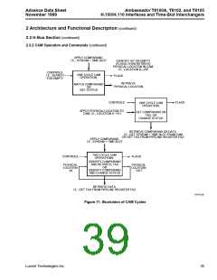
2.3.2 CAM Operation and Commands (continued)
If the user determines that a stream/time slot is no
longer valid, then the validity bit may be cleared by pre-
senting the connection address to the CAM and by
using the BKCn, break connection, command. The
connection that the user intends to break, which con-
sists of the time slot, and the stream plus control bits,
but not the tag, is transferred to the holding registers
prior to issuing this command. This is a two-cycle com-
mand: during the first cycle, the connection address is
presented to the CAM to identify which physical loca-
tion holds that connection address, and then, in the
second cycle, the validity bit is cleared for the identified
physical location. If there is a miss, it flags a no-match
error through the underflow bit in SYSERR.
The converse of the RDCn is the FENn, or find entry
command. It can be thought of as the first cycle of a
BKCn command. Only time slot and stream plus con-
trol bits are necessary for identifying the location. The
tag is not needed. The values returned (in sequence)
from two consecutive IDR reads (T8102, T8105 only)
or just one read (T8100A) (see Section 3.4.2 Setting
Up H-Bus Connections on page 75 for more details) to
the IDR is the physical location of the entry in the CAM
block, bits [7:0] then bit 8, if it is found. If the entry is not
found, then the underflow error bit in the SYSERR reg-
ister will be set. FENn is a one-cycle command.
Note: A complete connection break requires two
BKCn commands, one for each half of the con-
nection, as with the MKCn command.
The clear location (upper/lower) command, CLLn, is a
one-cycle command. The LAR contains the physical
address (i.e., the physical CAM location) to be cleared
(when AMR bit 5 equals 1, the lower bits, 0—255, are
cleared; when 0, the upper bits, 256—511, are
cleared). When it is presented to the CAM, the validity
bit is cleared, returning the location to an empty status
(i.e., it becomes available for new make connection
commands). The CLLn can also be regarded as the
second cycle of a break connection command. CLLn is
valuable if several outputs are driven from a common
input (broadcast) and the user wishes to break one of
the output connections, but leave the others intact.
When the physical location in the CAM is identified,
either by software tracking or by use of the find entry
command (later in this section), then the CLLn can be
issued.
RSCn is the reset CAM command, and this renders all
locations in one CAM block invalid. This can be consid-
ered a CLLn for all locations in the CAM. Two special
resets are the RCH command, which resets only the
holding registers, and the CI command, which resets
all three CAM blocks and the holding registers. All
resets are one-cycle.
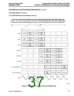
2.3.3 H-Bus Access
There are 32 bidirectional pins available for accessing
the H-bus. The direction of the pins is selected by the
CAM read and write bits. Data rates for the pins are
selected in accordance with the H.100/H.110 specifica-
tions. Unassigned time slots on the H-bus are 3-stated.
Details about rate selection are provided below. Two
bits of the 13-bit address are used to select the CAM
block as indicated in Figure 9. The remaining
11 bits plus a read/write bit form a comparand that is
stored in a CAM location.
36
Lucent Technologies Inc.

 AGERE [ AGERE SYSTEMS ]