Data Sheet
March 1997
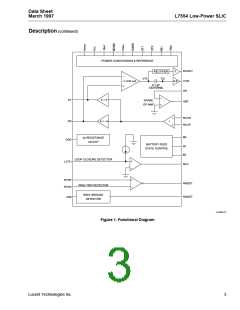
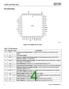
L7554 Low-Power SLIC
Recommended Operating Conditions
Parameter
Ambient Temperature
Min
–40
4.75
Typ
—
Max
85
Unit
°C
V
VCC Supply Voltage
5.0
5.25
VBAT Supply Voltage:
L7554AP
L7554BP
V
–24
–24
–40
–48
–60
–72
V
mA
mA
Vrms
Ω
Loop Closure Threshold-detection Programming Range
dc Loop Current-limit Programming Range
On- and Off-hook 2-wire Signal Level
—
5
10
40
1
ILIM
45
—
2.2
ac Termination Impedance Programming Range
150
600
1300
Electrical Characteristics
Minimum and maximum values are testing requirements.Typical values are characteristic of the device and are the
result of engineering evaluations. Typical values are for information purposes only and are not part of the testing
requirements. Minimum and maximum values apply across the entire temperature range (–40 °C to +85 °C) and
the entire battery range unless otherwise specified. Typical is defined as 25 °C, VCC = 5.0 V, VBAT = –48 V, and
ILIM = 40 mA. Positive currents flow into the device. Test circuit is Figure 4 unless noted.
Table 4. Power Supply
Parameter
Min
Typ
Max
Unit
Power Supply—Powerup, No Loop Current
ICC
IBAT (VBAT = –48 V)
—
—
—
4.1
–3.0
165
4.8
–3.5
191
mA
mA
mW
Power Dissipation (VBAT = –48 V)
Power Supply—Low-Power Scan, Forward Bat, No Loop
Current
ICC
—
—
—
2.7
–1.4
82
3.7
–1.7
100
mA
mA
mW
IBAT (VBAT = –48 V)
Power Dissipation (VBAT = –48 V)
Power Supply Rejection 500 Hz to 3 kHz
(See Figures 5, 6, 15, and 16.)1
VCC
VBAT
35
45
—
—
—
—
dB
dB
Thermal Protection Shutdown (Tjc)
—
—
175
47
—
—
°C
Thermal Resistance, Junction to Ambient (θJA)
°C/W
1. This parameter is not tested in production. It is guaranteed by design and device characterization.
Lucent Technologies Inc.
7

 AGERE [ AGERE SYSTEMS ]