AD9834
THEORY OF OPERATION
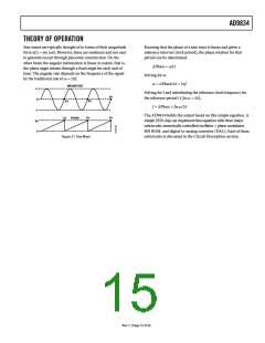
Sine waves are typically thought of in terms of their magnitude
form a(t) = sin (ωt). However, these are nonlinear and not easy
to generate except through piecewise construction. On the
other hand, the angular information is linear in nature, that is,
the phase angle rotates through a fixed angle for each unit of
time. The angular rate depends on the frequency of the signal
by the traditional rate of ω = 2πf.
Knowing that the phase of a sine wave is linear and given a
reference interval (clock period), the phase rotation for that
period can be determined.
ΔPhase = ωΔt
Solving for ω,
ω = ΔPhase/Δt = 2πf
MAGNITUDE
+1
Solving for f and substituting the reference clock frequency for
the reference period (1/fMCLK = Δt),
6π
0
4π
2π
f = ΔPhase × fMCLK/2π
–1
2p
0
The AD9834 builds the output based on this simple equation. A
simple DDS chip can implement this equation with three major
subcircuits: numerically controlled oscillator + phase modulator,
SIN ROM, and digital-to-analog converter (DAC). Each of these
subcircuits is discussed in the Circuit Description section.
6π
4π
2π
PHASE
Figure 27. Sine Wave
Rev. C | Page 15 of 36

 ADI [ ADI ]