Data Sheet
AD5940
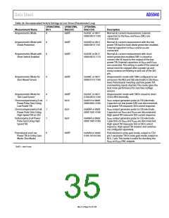
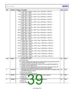
Table 20. Recommended Switch Settings in Low Power Potentiostat Loop
LPDACCON0,
Bit 5
LPDACSW0,
Bits[5:0]
LPTIASW0,
Bits[13:0]
Measurement Name
Description
Amperometric Mode
0
0xXX1
0x302C or 0b11
0000 0010 1100
Normal dc current measurement. External
capacitors to the VBIAS0 and VZERO0 DACs are
connected.
Normal dc current measurement with the low
power TIA back to back diode protection enabled.
External capacitors to VBIAS0 and VZERO0 are
connected.
Normal dc current measurement with short
switch protection enabled. SW1 is closed to
connect the SE input to the output of the low
power TIA. External capacitors to VBIAS0 and VZERO0
are connected. This setting is useful if the external
sensor must be charged after a power-up and
many currents are flowing in and out of the SE0
pin.
Amperometric mode with SW6 configured to set
sensorson the RE0 and SE0 electrodes to the VBIAS0
level. Potentiostat inverting and low power TIA
noninverting inputs shorted. This mode gives the
best noise performance for zero bias voltage
sensors.
Amperometric Mode with
Diode Protection
0
0xXX1
0x302D or 0b11
0000 0010 1101
Amperometric Mode with
Short Switch Enabled
0
0
0xXX1
0x302E or 0b11
0000 0010 1110
Amperometric Mode for
Zero Biased Sensor
0xXX1
0x306C or 0b11
0000 0110 1100
Amperometric Mode for
Two-Lead Sensor
Chronoamperometry (Low
Power Pulse Test) Using
Low Power TIA
0
1
0xXX1
0x32
0x342C or 0b11
0100 0010 1100
0x0014 or 0b00
0000 0001 0100
Amperometric mode with SW10 closed to short
CE0 to RE0 internally.
VBIAS0 output generates pulse to CE0 electrode.
Capacitors on low power DACs are disconnected.
Low power TIA measures SE0 current response.
Chronoamperometry (Full
Power Pulse Test) Using
High Speed TIA on SE0
Voltammetry (Full Power
Pulse Test) Using High
Speed TIA
1
1
0x31
0x31
0x0094 or 0b00
0000 1001 0100
VBIAS0 output generates pulse to CE0 electrode.
Capacitors on VBIAS0 and VZERO0 are disconnected.
High speed TIA measures SE0 current response.
0x0094 or 0b00
0000 1001 0100
VBIAS0 output generates pulse to CE0 electrode.
Capacitors on VBIAS0 and VZERO0 are disconnected.
High speed TIA measures SE0 or DE0 current
response. High speed TIA resistors and switches
are configured separately.
Potentiostat in unity-gain mode, output to CE0
pin. Low power TIA in unity-gain mode, output to
RC0_1 pin. This mode is useful for checking the
VBIAS0 or VZERO0 DAC outputs.
Potentiostat and Low
Power TIA in Unity-Gain
Mode (Test Mode)
0
0xXX1
0x04A4 or 0b00
0100 1010 0100
1 0xXX = don’t care.
Rev. 0 | Page 35 of 130

 ADI [ ADI ]