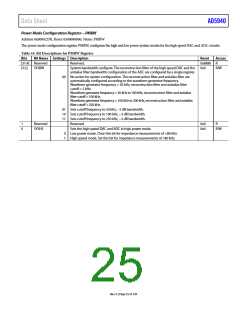
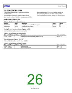
Data Sheet
AD5940
RELATIONSHIP BETWEEN THE 12-BIT AND 6-BIT
OUTPUTS
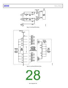
V
BIAS
+
–
DUAL
OUTPUT
DAC
CE0
RE0
SE0
PA
V
ZERO
The 12-bit and 6-bit outputs are mostly independent. However,
the selected 12-bit value does have a loading effect on the 6-bit
output that must be compensated for in user code, particularly
when the 12-bit output level is greater than the 6-bit output.
SENSOR
When the 12-bit output is less than the 6-bit output,
12-Bit DAC Output Voltage = 0.2 V + (LPDACDAT0,
Bits[11:0] × 12-BIT_LSB_DAC)
+
LPTIA
–
6-Bit DAC Output Voltage = 0.2 V + (LPDACDAT0,
Bits[17:12] × 6-BIT_LSB_DAC) – 12-BIT_LSB_DAC)
R
TIA
When the 12-bit output is ≥ the 6-bit output,
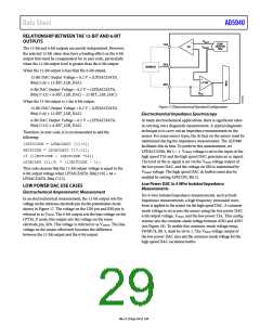
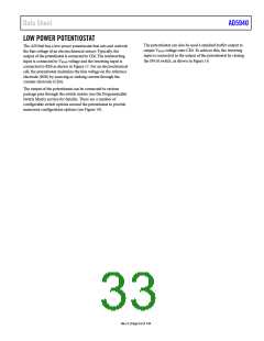
Figure 17. Electrochemical Standard Configuration
12-Bit DAC Output Voltage = 0.2 V + (LPDACDAT0,
Bits[11:0] × 12-BIT_LSB_DAC)
Electrochemical Impedance Spectroscopy
6-Bit DAC Output Voltage = 0.2 V + (LPDACDAT0,
Bits[17:12] × 6-BIT_LSB_DAC)
In many electrochemical applications, there is significant value
in carrying out a diagnostic measurement. A typical diagnostic
technique is to carry out an impedance measurement on the
sensor. For some sensor types, the dc bias on the sensor must be
maintained during the impedance measurement. The AD5940
facilitates this dc bias. To perform this measurement, set
LPDACCON0, Bit 5 = 1. VZERO0 voltage is set to the input of the
high speed TIA and the high speed DAC generates an ac signal.
The level of the ac signal is set via the VBIAS0 voltage output of
the low power DAC, and the voltage on SE0 is maintained by
Therefore, in user code, it is recommended to add the
following:
12BITCODE = LPDACDAT0 [11:0];
6BITCODE = LPDACDAT0 [17:12];
if (12BITCODE < (6BITCODE *64))
LPDACDAT [11:0] = (12BITCODE – 1);
This code ensures that the 12-bit output voltage is equal to the
6-bit output voltage when LPDACDAT0, Bits[11:0] = 64 ×
LPDACDAT0, Bits[17:12].
V
ZERO0 voltage. The high speed DAC dc buffers must also be
enabled by setting AFECON, Bit 21.
Low Power DAC in 4-Wire Isolated Impedance
Measurements
LOW POWER DAC USE CASES
Electrochemical Amperometric Measurement
For 4-wire isolated impedance measurements, such as body
impedance measurements, a high frequency sinusoidal wave-
form is applied to the sensor via the high speed DAC. A common-
mode voltage is set across the sensor using the low power DAC
6-bit output voltage, VZERO, and the low power TIA. This config-
uration sets the common-mode voltage between AIN2 and AIN3
(see Figure 18). To enable this common-mode voltage setup,
SWMUX, Bit 3, must be set to 1. The VBIAS0 voltage output of
the low power DAC also sets the common-mode voltage for the
high speed DAC excitation buffer.
In an electrochemical measurement, the 12-bit output sets the
voltage on the reference electrode pin via the potentiostat circuit
shown in Figure 17. The voltage on the CE0 pin and RE0 pin is
referred to as VBIAS0. The 6-bit output sets the bias voltage on the
LPTIA_P node; this output sets the voltage on the sense
electrode pin, SE0. This voltage is referred to as VZERO0. The bias
voltage on the sensor effectively becomes the difference
between the 12-bit output and the 6-bit output.
Rev. 0 | Page 29 of 130

 ADI [ ADI ]