Data Sheet
AD5940
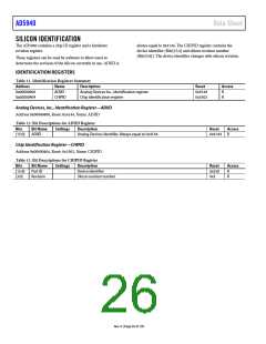
Power Mode Configuration Register—PMBW
Address 0x000022F0, Reset: 0x00088800, Name: PMBW
The power mode configuration register, PMBW, configures the high and low power system modes for the high speed DAC and ADC circuits.
Table 10. Bit Descriptions for PMBW Register
Bits
Bit Name Settings Description
Reset
0x8880
0x0
Access
R
R/W
[31:4] Reserved
[3:2]
Reserved.
SYSBW
System bandwidth configure. The reconstruction filter of the high speed DAC and the
antialias filter bandwidth configuration of the ADC are configured by a single register.
00 No action for system configuration. The reconstruction filter and antialias filter are
automatically configured according to the waveform generator frequency.
Waveform generator frequency = 50 kHz, reconstruction filter and antialias filter
cutoff = 5 kHz.
Waveform generator frequency = 50 kHz to 100 kHz, reconstruction filter and antialias
filter cutoff = 100 kHz.
Waveform generator frequency = 100 kHz to 200 kHz, reconstruction filter and antialias
filter cutoff = 250 kHz.
01 Sets cutoff frequency to 50 kHz, −3 dB bandwidth.
10 Sets cutoff frequency to 100 kHz, −3 dB bandwidth.
11 Sets cutoff frequency to 250 kHz, −3 dB bandwidth.
Reserved.
1
0
Reserved
SYSHS
0x0
0x0
R
R/W
Sets the high speed DAC and ADC in high power mode.
0
1
Low power mode. Clear this bit for impedance measurements of <80 kHz.
High speed mode. Set this bit for impedance measurements of >80 kHz.
Rev. 0 | Page 25 of 130

 ADI [ ADI ]