ADV7180
Register Select (SR7 to SR0)
REGISTER ACCESS
The MPU can write to or read from all of the ADV7180
registers except the subaddress register, which is write only. The
subaddress register determines which register the next read or
write operation accesses. All communications with the part
through the bus start with an access to the subaddress register.
Then a read/write operation is performed from or to the target
address, which increments to the next address until a stop
command on the bus is performed.
These bits are set up to point to the required starting address.
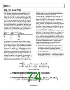
I2C SEQUENCER
An I2C sequencer is used when a parameter exceeds eight bits
and is therefore distributed over two or more I2C registers, for
example, HSB [11:0].
When such a parameter is changed using two or more I2C write
operations, the parameter may hold an invalid value for the
time between the first I2C being completed and the last I2C
being completed. In other words, the top bits of the parameter
may hold the new value while the remaining bits of the parameter
still hold the previous value.
To avoid this problem, the I2C sequencer holds the updated bits
of the parameter in local memory, and all bits of the parameter
are updated together once the last register write operation has
completed.
The correct operation of the I2C sequencer relies on the
following:
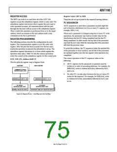
REGISTER PROGRAMMING
The following sections describe the configuration for each
register. The communication register is an 8-bit, write-only
register. After the part has been accessed over the bus and a
read/write operation is selected, the subaddress is set up. The
subaddress register determines to or from which register the
operation takes place. Table 101 lists the various operations
under the control of the subaddress register for the control port.
SUB_USR_EN, Address 0x0E [5]
This bit splits the register map at Register 0x40.
•
All I2C registers for the parameter in question must be
written to in order of ascending addresses. For example, for
HSB[10:0], write to Address 0x34 first, followed by 0x35,
and so on.
USER MAP
USER SUB MAP
2
COMMON I C SPACE
ADDRESS 0x00 ≥ 0x3F
•
No other I2C can take place between the two (or more) I2C
writes for the sequence. For example, for HSB[10:0], write
to Address 0x34 first, immediately followed by 0x35, and
so on.
ADDRESS 0x0E BIT 5 = 0b
ADDRESS 0x0E BIT 5 = 1b
2
2
I C SPACE
I C SPACE
ADDRESS 0x40 ≥ 0xFF
ADDRESS 0x40 ≥ 0x9C
NORMAL REGISTER SPACE
INTERRUPT AND VDP REGISTER SPACE
Figure 50. Register Access—User Map and User Sub Map
Rev. A | Page 75 of 112

 ADI [ ADI ]