ADV7180
GPO CONTROL
The ADV7180 LQFP-64 has four general-purpose outputs
(GPO). These outputs allow the user to control other devices in
a system via the I2C port of the ADV7180 LQFP-64.
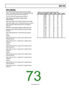
Table 99. General-Purpose Output Truth Table
GPO_Enable GPO[3:0] GPO3 GPO2 GPO1
GPO0
0
1
1
1
1
1
1
1
1
1
1
1
1
1
1
1
1
XXXX
0000
0001
0010
0011
0100
0101
0110
0111
1000
1001
1010
1011
1100
1101
1110
1111
Z
0
0
0
0
0
0
0
0
1
1
1
1
1
1
1
1
Z
0
0
0
0
1
1
1
1
0
0
0
0
1
1
1
1
Z
0
0
1
1
0
0
1
1
0
0
1
1
0
0
1
1
Z
0
1
0
1
0
1
0
1
0
1
0
1
0
1
0
1
The ADV7180 LFCSP-40 does not have GPO pins.
GPO_Enable, General Purpose Output Enable,
Address 0x59[4]
When GPO_Enable is set to 0, all four GPO pins are three-stated.
When GPO_Enable is set to 1, all four GPO pins are in a driven
state. The polarity output from each GPO is controlled by
GPO[3:0].
GPO[3:0], General Purpose Outputs, Address 0x59 [3:0]
Individual control of the four GPO ports is achieved using
GPO[3:0].
GPO_Enable must be set to 1 for the GPO pins to become
active.
GPO[0]
When GPO[0] is set to 0, a Logic Level 0 is output from the
GPO0 pin [Pin 13]
When GPO[0] is set to 1, a Logic Level 1 is output from the
GPO0 pin.
GPO[1]
When GPO[1] is set to 0, a Logic Level 0 is output from the
GPO1 pin [Pin 12].
When GPO[1] is set to 1, a Logic Level 1 is output from the
GPO1 pin.
GPO[2]
When GPO[2] is set to 0, a Logic Level 0 is output from the
GPO2 pin [Pin 56].
When GPO[2] is set to 1, a Logic Level 1 is output from the
GPO2 pin.
GPO[3]
When GPO[3] is set to 0, a Logic Level 0 is output from the
GPO3 pin [Pin 55].
When GPO[3] is set to 1, a Logic Level 1 is output from the
GPO3 pin.
Rev. A | Page 73 of 112

 ADI [ ADI ]