ADV7180
VS and FIELD Configuration
HVSTIM, Horizontal VS Timing, Address 0x31 [3]
The following controls allow the user to configure the behavior
of the VS and FIELD output pins, as well as the generation of
embedded AV codes.
The HVSTIM bit allows the user to select where the VS signal is
asserted within a line of video. Some interface circuitry may
require VS to go low while HS is low.
Note that the ADV7180 LQFP-64 has separate VS and FIELD pins.
The ADV7180 LFCSP-40 does not have separate VS and FIELD
pins, but can output either one on Pin 37, the VS/FIELD pin.
When HVSTIM is 0 (default), the start of the line is relative to
HSE.
When HVSTIM is 1, the start of the line is relative to HSB.
VSYNC/FIELD SELECT, Address 0x58 [0]
VSBHO, VS Begin Horizontal Position Odd, Address 0x32 [7]
This feature is used for the ADV7180 LFCSP-40 (ADV7180BCPZ)
only. The polarity of this bit determines what signal appears on
the VS/FIELD pin.
The VSBHO and VSBHE bits select the position within a line at
which the VS pin (not the bit in the AV code) becomes active.
Some follow-on chips require the VS pin to change state only
when HS is high/low.
When this bit is set to 0 (default), the FIELD signal is output.
When this bit is set to 1, the VSYNC signal is output.
When VSBHO is 0 (default), the VS pin goes high at the middle
of a line of video (odd field).
The ADV7180 LQFP-64 (ADV7180BSTZ) has dedicated FIELD
and VSYNC pins.
When VSBHO is 1, the VS pin changes state at the start of a line
(odd field).
ADV encoder-compatible signals via NEWAVMODE are
VSBHE, VS Begin Horizontal Position Even, Address 0x32 [6]
•
•
•
•
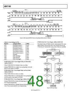
PVS, PF
The VSBHO and VSBHE bits select the position within a line at
which the VS pin (not the bit in the AV code) becomes active.
Some follow-on chips require the VS pin to only change state
when HS is high/low.
HVSTIM
VSBHO, VSBHE
VSEHO, VSEHE
When VSBHE is 0 (default), the VS pin goes high at the middle
of a line of video (even field).
For NTSC control,
•
•
NVBEGDELO, NVBEGDELE, NVBEGSIGN, NVBEG[4:0]
When VSBHE is 1, the VS pin changes state at the start of a line
(even field).
NVENDDELO, NVENDDELE, NVENDSIGN,
NVEND[4:0]
VSEHO, VS End Horizontal Position Odd, Address 0x33 [7]
•
NFTOGDELO, NFTOGDELE, NFTOGSIGN,
NFTOG[4:0]
The VSEHO and VSEHE bits select the position within a line at
which the VS pin (not the bit in the AV code) becomes active.
Some follow-on chips require the VS pin to change state only
when HS is high/low.
For PAL control,
•
•
•
PVBEGDELO, PVBEGDELE, PVBEGSIGN, PVBEG[4:0]
When VSEHO is 0 (default), the VS pin goes low (inactive) at
the middle of a line of video (odd field).
PVENDDELO, PVENDDELE, PVENDSIGN, PVEND[4:0]
PFTOGDELO, PFTOGDELE, PFTOGSIGN, PFTOG[4:0]
When VSEHO is 1, the VS pin changes state at the start of a line
(odd field).
NEWAVMODE, New AV Mode, Address 0x31 [4]
When NEWAVMODE is 0, EAV/SAV codes are generated to
suit Analog Devices encoders. No adjustments are possible.
VSEHE, VS End Horizontal Position Even, Address 0x33 [6]
The VSEHO and VSEHE bits select the position within a line at
which the VS pin (not the bit in the AV code) becomes active.
Some follow-on chips require the VS pin to only change state
when HS is high/low.
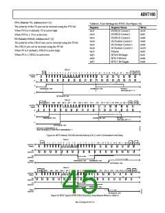
Setting NEWAVMODE to 1 (default) enables the manual position
of the VSYNC, FIELD, and AV codes using Register 0x34 to
Register 0x37 and Register 0xE5 to Register 0xEA. Default register
settings are CCIR656 compliant; see Figure 33 for NTSC and
Figure 38 for PAL. For recommended manual user settings,
see Table 61 and Figure 34 for NTSC and Table 62 and Figure 39
for PAL.
When VSEHE is 0 (default), the VS pin goes low (inactive) at
the middle of a line of video (even field).
When VSEHE is 1, the VS pin changes state at the start of a line
(even field).
Rev. A | Page 44 of 112

 ADI [ ADI ]