ADV7180
AV CODE INSERTION AND CONTROLS
This section describes the I2C-based controls that affect
In this output interface mode, the following assignment takes
place: Cb = FF, Y = 00, Cr = 00, and Y = AV.
•
•
•
Insertion of AV codes into the data stream
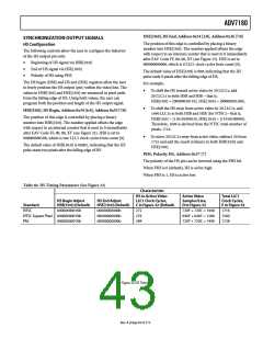
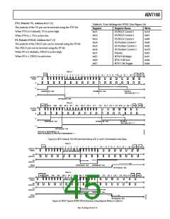
In a 16-bit output interface (ADV7180 LQFP-64 only) where Y
and Cr/Cb are delivered via separate data buses, the AV code is
spread over the whole 16 bits. The SD_DUP_AV bit allows the
user to replicate the AV codes on both buses, so the full AV
sequence can be found on the Y bus as well as on the Cr/Cb bus
(see Figure 31).
Data blanking during the vertical blank interval (VBI)
The range of data values permitted in the output data
stream
•
The relative delay of luma vs. chroma signals
Note that some of the decoded VBI data is inserted during the
horizontal blanking interval. See the Gemstar Data Recovery
section for more information.
When SD_DUP_AV is 0 (default), the AV codes are in single
fashion (to suit 8-bit interleaved data output).
When SD_DUP_AV is 1, the AV codes are duplicated (for
16-bit interfaces).
BT.656-4, ITU-R BT.656-4 Enable, Address 0x04 [7]
Between Revision 3 and Revision 4 of the ITU-R BT.656 standards,
the ITU has changed the toggling position for the V bit within
the SAV EAV codes for NTSC. The ITU-R BT.656-4 standard
bit allows the user to select an output mode that is compliant
with either the previous or new standard. For further information,
visit the International Telecommunication Union’s website.
VBI_EN, Vertical Blanking Interval Data Enable,
Address 0x03 [7]
The VBI enable bit allows data such as intercast and closed
caption data to be passed through the luma channel of the
decoder with a minimal amount of filtering. All data for Line 1
to Line 21 is passed through and available at the output port.
The ADV7180 does not blank the luma data and automatically
switches all filters along the luma data path into their widest
bandwidth. For active video, the filter settings for YSH and YPK
are restored.
Note that the standard change only affects NTSC and has no
bearing on PAL.
When ITU-R BT.656-4 is 0 (default), the ITU-R BT.656-3
specification is used. The V bit goes low at EAV of Line 10
and Line 273.
See the BL_C_VBI, Blank Chroma During VBI, Address 0x04
[2] section for information on the chroma path.
When ITU-R BT.656-4 is 1, the ITU-R BT.656-4 specification is
used. The V bit goes low at EAV of Line 20 and Line 283.
When VBI_EN is 0 (default), all video lines are filtered/scaled.
SD_DUP_AV, Duplicate AV Codes, Address 0x03 [0]
When VBI_EN is 1, only the active video region is
filtered/scaled.
Depending on the output interface width, it may be necessary to
duplicate the AV codes from the luma path into the chroma path.
In an 8-bit-wide output interface (Cb/Y/Cr/Y interleaved data),
the AV codes are defined as FF/00/00/AV, with AV being the
transmitted word that contains information about H/V/F.
SD_DUP_AV = 1
SD_DUP_AV = 0
16-BIT INTERFACE
16-BIT INTERFACE
8-BIT INTERFACE
Y DATA BUS
FF
FF
00
00
AV
AV
Y
00
AV
Y
Cb/Y/Cr/Y
INTERLEAVED
FF
00
00 AV Cb
Cr/Cb DATA BUS
00
00
Cb
FF
00
Cb
AV CODE SECTION
AV CODE SECTION
AV CODE SECTION
Figure 31. AV Code Duplication Control (ADV7180 LQFP-64 Only)
Rev. A | Page 41 of 112

 ADI [ ADI ]