ADV7180
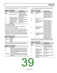
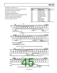
HSE[10:0], HS End, Address 0x34 [2:0], Address 0x36 [7:0]
SYNCHRONIZATION OUTPUT SIGNALS
The position of this edge is controlled by placing a binary
number into HSE[10:0]. The number applied offsets the edge
with respect to an internal counter that is reset to 0 immediately
after EAV Code FF, 00, 00, XY (see Figure 32). HSE is set to
00000000000b, which is 0 LLC1 clock cycles from count [0].
HS Configuration
The following controls allow the user to configure the behavior
of the HS output pin only:
•
•
•
Beginning of HS signal via HSB[10:0]
End of HS signal via HSE[10:0]
Polarity of HS using PHS
The default value of HSE[10:0] is 000, indicating that the HS
pulse ends 0 pixels after the falling edge of HS.
The HS begin (HSB) and HS end (HSE) registers allow the user
to freely position the HS output (pin) within the video line. The
values in HSB[10:0] and HSE[10:0] are measured in pixel units
from the falling edge of HS. Using both values, the user can
program both the position and length of the HS output signal.
For example,
•
To shift the HS toward active video by 20 LLC1s, add
20 LLC1s to both HSB and HSE—that is,
HSB[10:0] = [00000010110], HSE[10:0] = [00000010100].
•
To shift the HS away from active video by 20 LLC1s, add
1696 LLC1s to both HSB and HSE (for NTSC)—that is,
HSB[10:0] = [11010100010], HSE[10:0] = [11010100000].
Therefore, 1696 is derived from the NTSC total number of
pixels, 1716.
HSB[10:0], HS Begin, Address 0x34 [6:4], Address 0x35 [7:0]
The position of this edge is controlled by placing a binary
number into HSB[10:0]. The number applied offsets the edge
with respect to an internal counter that is reset to 0 immediately
after EAV Code FF, 00, 00, XY (see Figure 32). HSB is set to
00000000010b, which is two LLC1 clock cycles from count [0].
•
To move 20 LLC1s away from active video, subtract 20 from
1716 and add the result in binary to both HSB[10:0] and
HSE[10:0].
The default value of HSB[10:0] is 0x002, indicating that the HS
pulse starts two pixels after the falling edge of HS.
PHS, Polarity HS, Address 0x37 [7]
The polarity of the HS pin can be inverted using the PHS bit.
When PHS is 0 (default), HS is active high.
When PHS is 1, HS is active low.
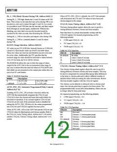
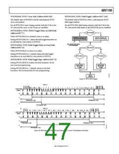
Table 60. HS Timing Parameters (See Figure 32)
Characteristic
HS to Active Video
LLC1 Clock Cycles,
C in Figure 32 (Default)
Active Video
Samples/Line,
D in Figure 32
Total LLC1
Clock Cycles,
E in Figure 32
HS Begin Adjust
HSB[10:0] (Default)
HS End Adjust
HSE[10:0] (Default)
Standard
NTSC
00000000010b
00000000000b
00000000000b
00000000000b
272
276
284
720Y + 720C = 1440
640Y + 640C = 1280
720Y + 720C = 1440
1716
1560
1728
NTSC Square Pixel 00000000010b
PAL 00000000010b
Figure 32. HS Timing
Rev. A | Page 43 of 112

 ADI [ ADI ]