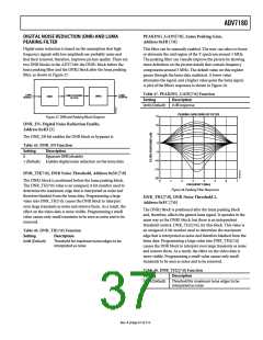
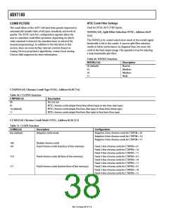
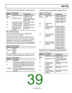
ADV7180
PEAKING_GAIN[7:0], Luma Peaking Gain,
Address 0xFB [7:0]
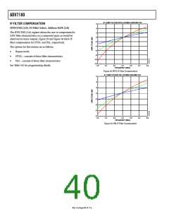
DIGITAL NOISE REDUCTION (DNR) AND LUMA
PEAKING FILTER
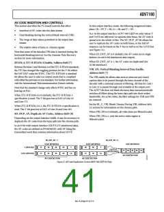
Digital noise reduction is based on the assumption that high
frequency signals with low amplitude are probably noise and
that their removal, therefore, improves picture quality. There are
two DNR blocks in the ADV7180: the DNR1 block before the
luma peaking filter and the DNR2 block after the luma peaking
filter, as shown in Figure 27.
This filter can be manually enabled. The user can select to boost
or attenuate the mid region of the Y spectrum around 3 MHz.
The peaking filter can visually improve the picture by showing
more definition on the picture details that contain frequency
components around 3 MHz. The default value on this register
passes through the luma data unaltered. A lower value
attenuates the signal, and a higher value gains the luma signal.
A plot of the filter’s responses is shown in Figure 28.
Table 47. PEAKING_GAIN[7:0] Function
LUMA
SIGNAL
LUMA
OUTPUT
LUMA PEAKING
FILTER
DNR2
DNR1
Setting
Description
0x40 (Default)
0 dB response
PEAKING GAIN USING BP FILTER
15
10
5
Figure 27. DNR and Peaking Block Diagram
DNR_EN, Digital Noise Reduction Enable,
Address 0x4D [5]
The DNR_EN bit enables the DNR block or bypasses it.
0
Table 45. DNR_EN Function
Setting
Description
–5
–10
–15
0
Bypasses DNR (disable)
Enables digital noise reduction on the luma data
1 (Default)
DNR_TH[7:0], DNR Noise Threshold, Address 0x50 [7:0]
–20
0
The DNR1 block is positioned before the luma peaking block.
The DNR_TH[7:0] value is an unsigned, 8-bit number used to
determine the maximum edge that is interpreted as noise and
therefore blanked from the luma data. Programming a large
value into DNR_TH[7:0] causes the DNR block to interpret
even large transients as noise and remove them. As a result, the
effect on the video data is more visible. Programming a small
value causes only small transients to be seen as noise and to be
removed.
1
2
3
4
5
6
7
FREQUENCY (MHz)
Figure 28. Peaking Filter Responses
DNR_TH2[7:0], DNR Noise Threshold 2,
Address 0xFC [7:0]
The DNR2 block is positioned after the luma peaking block
and, therefore, affects the gained luma signal. It operates in the
same way as the DNR1 block, but there is an independent
threshold control, DNR_TH2[7:0], for this block. This value is
an unsigned, 8-bit number used to determine the maximum
edge that is interpreted as noise and therefore blanked from the
luma data. Programming a large value into DNR_TH2[7:0]
causes the DNR block to interpret even large transients as noise
and remove them. As a result, the effect on the video data is
more visible. Programming a small value causes only small
transients to be seen as noise and to be removed.
Table 46. DNR_TH[7:0] Function
Setting
Description
0x08 (Default)
Threshold for maximum luma edges to be
interpreted as noise
Table 48. DNR_TH2[7:0] Function
Setting
Description
0x04 (Default)
Threshold for maximum luma edges to be
interpreted as noise
Rev. A | Page 37 of 112

 ADI [ ADI ]