AD9364
Data Sheet
Pin No.
Type1 Mnemonic
Description
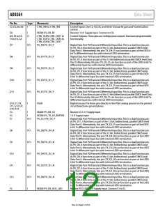
J12
I/O
P1_D1/RX_D0_P
Digital Data Port P1/Receive Differential Output Bus. This is a dual function pin.
As P1_D1, it functions as part of the 12-bit bidirectional parallel CMOS level
Data Port 1. Alternatively, this pin (RX_D0_P) can function as part of the LVDS
6-bit Rx differential output bus with internal LVDS termination.
K1, L1
I
RXC_P, RXC_N
Receive Channel Differential Input C. Alternatively, each pin can be used as a
single-ended input. These inputs experience degraded performance above
3 GHz. Unused pins must be tied to ground.
K3
K4
K5
K6
K7
I
I
I
I
VDDA1P3_TX_SYNTH
VDDA1P3_BB
RESETB
SPI_ENB
P1_D8/RX_D4_N
1.3 V Supply Input.
1.3 V Supply Input.
Asynchronous Reset. Logic low resets the device.
SPI Enable Input. Set this pin to logic low to enable the SPI bus.
Digital Data Port P1/Receive Differential Output Bus. This is a dual function pin.
As P1_D8, it functions as part of the 12-bit bidirectional parallel CMOS level
Data Port 1. Alternatively, this pin (RX_D4_N) can function as part of the LVDS
6-bit Rx differential output bus with internal LVDS termination.
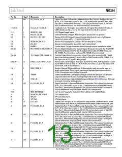
I/O
K8
I/O
I/O
I/O
I/O
I
P1_D6/RX_D3_N
P1_D4/RX_D2_N
P1_D2/RX_D1_N
P1_D0/RX_D0_N
RBIAS
Digital Data Port P1/Receive Differential Output Bus. This is a dual function pin.
As P1_D6, it functions as part of the 12-bit bidirectional parallel CMOS level
Data Port 1. Alternatively, this pin (RX_D3_N) can function as part of the LVDS
6-bit Rx differential output bus with internal LVDS termination.
Digital Data Port P1/Receive Differential Output Bus. This is a dual function pin.
As P1_D4, it functions as part of the 12-bit bidirectional parallel CMOS level
Data Port 1. Alternatively, this pin (RX_D2_N) can function as part of the LVDS
6-bit Rx differential output bus with internal LVDS termination.
Digital Data Port P1/Receive Differential Output Bus. This is a dual function pin.
As P1_D2, it functions as part of the 12-bit bidirectional parallel CMOS level
Data Port 1. Alternatively, this pin (RX_D1_N) can function as part of the LVDS
6-bit Rx differential output bus with internal LVDS termination.
Digital Data Port P1/Receive Differential Output Bus. This is a dual function pin.
As P1_D0, it functions as part of the 12-bit bidirectional parallel CMOS level Data
Port 1. Alternatively, this pin (RX_D0_N) can function as part of the LVDS 6-bit Rx
differential output bus with internal LVDS termination.
K9
K10
K11
L4
Bias Input Reference. Connect this pin through a 14.3 kΩ (1% tolerance) resistor
to ground.
L5
L6
M1, M2
I
O
I
AUXADC
SPI_DO
RXA_ P, RXA_N
Auxiliary ADC Input. If this pin is unused, tie it to ground.
SPI Serial Data Output in 4-Wire Mode, High-Z in 3-Wire Mode.
Receive Channel Differential Input A. Alternatively, each pin can be used as a
single-ended input. Unused pins must be tied to ground.
M5
I
TX_MON
Transmit Channel Power Monitor Input. If this pin is unused, tie it to ground.
Transmit Channel Differential Output A. Unused pins must be tied to 1.3 V.
Transmit Channel Differential Output B. Unused pins must be tied to 1.3 V.
Reference Frequency Crystal Connections. When a crystal is used, connect it
between these two pins. When an external clock source is used, connect it to
XTALN and leave XTALP unconnected.
M7, M8
M9, M10
M11, M12
O
O
I
TXA_P, TXA_N
TXB_P, TXB_N
XTALP, XTALN
1 I is input, O is output, I/O is input/output, NC is not connected.
Rev. B | Page 14 of 32

 ADI [ ADI ]