AD7904/AD7914/AD7924
Data Sheet
SEQUENCER OPERATION
Figure 12 shows how to program the AD7904/AD7914/AD7924
to continuously convert on a sequence of consecutive channels
from Channel 0 to a selected final channel. To exit this mode of
operation and revert to the traditional mode of operation of a
multichannel ADC (as shown in Figure 11), ensure that the
WRITE bit = 1 and SEQ1 = SEQ0 = 0 on the next serial transfer.
The SEQ1 and SEQ0 bits in the control register allow the user to
select a mode of operation for the sequencer function. Table 10
outlines the three modes of operation of the sequencer.
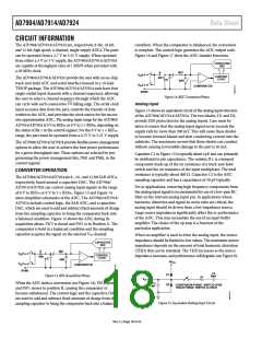
Figure 11 shows the traditional operation of a multichannel
ADC, where each serial transfer selects the next channel for
conversion. In this mode of operation, the sequencer function
is not used.
Table 10. Sequence Selection
SEQ1
SEQ0
Sequencer Function Description
0
X
Not used
The sequencer function is not used. The analog input channel selected for each individual
conversion is determined by the contents of the channel address bits, ADD1 and ADD0, in each
previous write operation. This mode of operation reflects the traditional operation of a multi-
channel ADC, without using the sequencer function, where each write to the AD7904/AD7914/
AD7924 selects the next channel for conversion (see Figure 11).
1
1
0
1
Used (not interrupted The sequencer function is not interrupted upon completion of the write operation. This config-
upon completion)
uration allows other bits in the control register to be altered between conversions while in a
sequence without terminating the cycle.
Continuous
conversions
This configuration is used in conjunction with the channel address bits, ADD1 and ADD0, to
program continuous conversions on a consecutive sequence of channels from Channel 0 to a
selected final channel that is specified by the channel address bits in the control register (see
Figure 12).
POWER ON
DUMMY CONVERSION
DIN: WRITE TO CONTROL REGISTER,
WRITE BIT = 1,
SELECT CODING, RANGE, AND POWER MODE.
SELECT CHANNEL ADD1, ADD0 FOR CONVERSION.
SEQ1 = 0, SEQ0 = x
CS
DOUT: CONVERSION RESULT FROM PREVIOUSLY
SELECTED CHANNEL ADD1, ADD0
DIN: WRITE TO CONTROL REGISTER,
CS
WRITE BIT = 1,
WRITE BIT = 1,
SEQ1 = 0, SEQ0 = x
SELECT CODING, RANGE, AND POWER MODE.
SELECT ADD1, ADD0 FOR CONVERSION.
SEQ1 = 0, SEQ0 = x
Figure 11. SEQ1 Bit = 0, SEQ0 Bit = x Flowchart
Rev. C | Page 16 of 32

 ADI [ ADI ]