AD73360
DSP SPORT Interrupts
DSP
MICROPROCESSOR
If SPORT interrupts are enabled, it is important to note that the
active signals on the frame sync pins do not necessarily corre-
spond with the positions in time of where SPORT interrupts are
generated.
I
V
C
C
DAC
DAC
TORQUE & FLUX
CONTROL LOOP
CALCULATIONS
I
THREE-
PHASE
MOTOR
V
B
B
DRIVE
CIRCUITRY
I
V
A
A
DAC
On ADSP-21xx processors, it is necessary to enable SPORT
interrupts and use Interrupt Service Routines (ISRs) to handle
Tx/Rx activity, while on the TMS320C5x processors it is pos-
sible to poll the status of the Rx and Tx registers, which means
that Rx/Tx activity can be monitored using a single ISR that
would ideally be the Tx ISR as the Tx interrupt will typically
occur before the Rx ISR.
ISOLATION
TORQUE
AMPLIFIERS
SETPOINT
FLUX
SETPOINT
V
V
IN1
IN2
AD73360
V
TRANSFORMATION
TO TORQUE &
FLUX
IN3
APPLICATIONS EXAMPLES
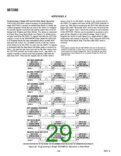
Vector Motor Control
CURRENT
V
V
V
IN4
COMPONENTS
IN5
The current drawn by a motor can be split into two compo-
nents: one produces torque and the other produces magnetic
flux. For optimal performance of the motor, these two compo-
nents should be controlled independently. In conventional
methods of controlling a three-phase motor, the current (or
voltage) supplied to the motor and the frequency of the drive are
the basic control variables. However, both the torque and flux
are functions of current (or voltage) and frequency. This cou-
pling effect can reduce the performance of the motor because,
for example, if the torque is increased by increasing the fre-
quency, the flux tends to decrease.
IN6
VOLTAGE
ATTENUATORS
Figure 30. Vector Motor Control Using the AD73360
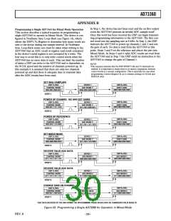
Industrial Power Metering
The AD73360 can be used to measure the voltage and current
in all three phases of a three-phase supply. The simultaneous
sampling architecture of the AD73360 is ideal for this applica-
tion where simultaneous sampling is critical to maintaining the
relative phase information between the three voltage and three
current phases. Figure 31 shows a block diagram of a three-
phase metering system. The VIN1, VIN2 and VIN3 channels are
used to measure the voltages in each phase (via voltage attenua-
tors). The current flowing in each phase can be detected by the
use of current-sensing isolation amplifiers, transformers or
Hall-effect sensors. VIN4, VIN5 and VIN6 are used to digitize
this information. A DSP microprocessor is used to perform
the mathematical calculations on the information provided by
the AD73360.
Vector control of an ac motor involves controlling phase in
addition to drive and current frequency. Controlling the phase
of the motor requires feedback information on the position of
the rotor relative to the rotating magnetic field in the motor.
Using this information, a vector controller mathematically trans-
forms the three-phase drive currents into separate torque and
flux components. The AD73360, with its six-channel simulta-
neous sampling capability, is ideally suited for use in vector
motor control applications.
A block diagram of a vector motor control application using the
AD73360 is shown in Figure 30. The position of the field is
derived by determining the current in each phase of the motor.
I
V
C
C
3
I
V
B
THREE-
PHASE
SUPPLY
B
2
V
IN1, VIN2 and VIN3 of the AD73360 are used to digitize this
I
information.
V
A
A
1
Simultaneous sampling is critical to maintain the relative phase
information between the channels. A current-sensing isolation
amplifier, transformer or Hall-effect sensor is used between the
motor and the AD73360. Rotor information is obtained by
ISOLATION
AMPLIFIERS
V
V
IN1
measuring the voltage from the three inputs to the motor. VIN4
,
IN2
V
IN5 and VIN6 of the AD73360 are used to obtain this informa-
AD73360
V
tion. A DSP microprocessor is used to perform the mathematical
transformations and control loop calculations on the informa-
tion fed back by the AD73360.
DSP
MICROPROCESSOR
IN3
V
V
V
IN4
IN5
IN6
VOLTAGE
ATTENUATORS
Figure 31. Three-Phase Power Metering
REV. B
–27–

 ADI [ ADI ]