AD73360
APPENDIX C
In Step 4, Device 2 will transmit the invalid ADC sample it
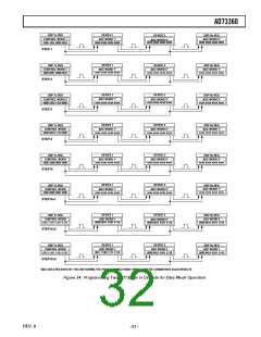
Configuring a Cascade of Two AD73360s to Operate in
Data Mode
received from Device 1 while receiving a control word from
Device 1 at the same time. Device 2 transmitting will cause the
DSP to transmit a control word for Device 1. This should be
similar to the control word transmitted in step 3 except that this
word is intended for Device 1. When transmission is complete
both devices have received instructions to power up all channels
and set the reference etc. Steps 3 and 4 can be repeated, as
necessary, to program other registers concerned with the analog
section.
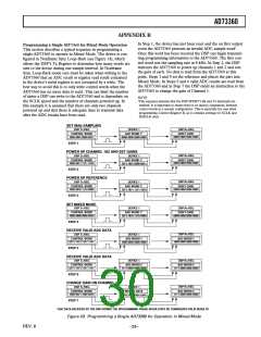
This section describes a typical sequence of control words that
would be sent to a cascade of two AD73360s to set them up for
operation. It is not intended to be a definitive initialization
sequence, but will show users the typical input/output events
that occur in the programming and operation phases1. This
description panel refers to Figure 34.
In Step 1, we have the first output sample event following de-
vice reset. The SDOFS signal is raised on both devices simulta-
neously, which prepares the DSP Rx register to accept the ADC
word from Device 2, while SDOFS from Device 1 becomes an
SDIFS to Device 2. As the SDOFS of Device 2 is coupled to
the DSP’s TFS and RFS, and to the SDIFS of Device 1, this
event also forces a new control word to be output from the DSP
Tx register to Device 1. The control word loaded to Device 1 is
addressed to Device 2 (i.e., the address field is 001). Device 1
will decrement the address field and pass it to Device 2 when
the next frame sync arrives. As the DSP is transmitting a control
word, Device 2 is outputting an invalid ADC word. (Note that
the AD73360 will not output valid ADC words until the device
is placed in either mixed mode or data mode. Any ADC values
received during the programming phase should be discarded.)
At the same time, Device 1 will output its ADC result to Device
2. Once all the data has been transferred, Device 1 will contain
an instruction for Device 2 (which instructs the part to set its
SCLK frequency), Device 2 will have received an ADC result
from Device 1 and the DSP will have received an ADC result
from Device 2.
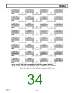
Step N is the first stage of changing the operating modes of the
devices to Data Mode. As Device 2 outputs an ADC word the
DSP will transmit a control word intended for CRA of Device 2
to Device 1. As in Step 1, Device 1 will decrement the address
field and pass on the control word on the next frame sync.
In Step N + 1, Device 2 transmits an ADC word it received
from Device 1. This causes the DSP to transmit a control word
to Device 1 (intended for its CRA register). At the same time
Device 2 is receiving its control word from Device 1. Both de-
vices simultaneously receive commands to change from Program
Mode to Data Mode and the number of devices in the cascade is
also programmed here.
In Step N + 2, we begin to receive valid ADC data. Note that
the data comes from the last device in the chain (Device 2) first.
As Device 2 transmits its ADC data it is receiving ADC data
from Device 1. Any data transmitted from the DSP will be ig-
nored from now on.
In Step N + 3, Device 2 has received an ADC sample from
Device 1 and transmits it to the DSP. Steps N + 2 and N + 3
are repeated as long as samples are required.
In Step 2, Device 2 will begin transmitting the ADC word it
received from Device 1. This will cause the DSP to transmit a
second command word, which tells Device 1 to change its serial
clock. Simultaneously, Device 1 passes the first control word on
to Device 2. In this manner both devices receive control word
instructions and act upon them at the same time.
NOTE
1This sequence assumes that the DSP SPORT’s Rx and Tx interrupts are
enabled. It is important to ensure that there is no latency (separation) between
control words in a cascade configuration. This is especially the case when
programming Control Register B as it contains settings for SCLK and DMCLK
rates.
Step 3 is similar to Step 1 in that the DSP transmits a control
word for Device 2. Device 1 passes an invalid ADC result to
Device 2 and Device 2 transmits its own invalid ADC result to
the DSP.
–30–
REV. B

 ADI [ ADI ]