The format of the captured data varies according to the register
select fields. Data captured from the mult_out setting is in 1.23
twos complement format so that a full-scale input signal will
produce a full-scale digital output (assuming no processing). If
the parameters are set such that the input-to-output gain is more
than 0 dB, then the digital output will be clipped.
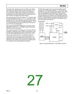
The SPI capture registers can be accessed by reading from SPI
Locations 261 (for SPI Capture Register 1) or 262 (for SPI Cap-
ture Register 2).The other two data capture registers (data capture
serial out) automatically transfer their data to the data capture
serial out (DCSOUT) pin. DCSOUT Capture Register 1 is pres-
ent in the left data slot (as defined by the serial input format), and
DCSOUT Capture Register 2 is present in the right data slot.The
format for writing to the SPI data capture setup registers is given
in the SPI section of this data sheet.
Data captured from the DB_OUT setting is in 5.19 format, where
the actual rms dB level is equal to –87 + (3
DB_OUT). In this
equation, DB_OUT is the value that is captured. It follows that in
this data format, the actual output readings will range from –87 dB
to +9 dB
.
T
he AD1954 uses the convention that 0 dB is the rms
value of the full-scale digital signal.
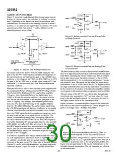
dB LEVEL METERS
LRCLK
EXT DACs
BCLK
Data captured using the MDI setting is in 3.21 format. A 0 dB
digital input will produce a –12 dB digital output, assuming the
AD1954 is set for no processing.
Data captured using the MCI setting is in 2.20 format.This data
is generally a signal gain or filter coefficient, and therefore it does
not make sense to talk about the input-to-output gain. A coeffi-
cient of 01000000000000000000 corresponds to a gain of 1.0.
DCSOUT
5.1
CHANNEL
OUTPUT
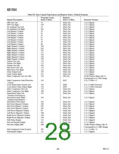
The data that must be written to set up the data capture is a
concatenation of the 9-bit program count index with the 2-bit
register select field. Refer toTable XX to find the capture count
and register select numbers that correspond to the desired point
to be monitored in the default signal processing flow.
MICRO-
CONTROLLER
AD1954
Figure 19. Typical Application of Data Capture Feature
REV. A

 ADI [ ADI ]