LRCLK
BCLK
RIGHT CHANNEL
LEFT CHANNEL
SDATA
MSB
LSB
MSB
LEFT-JUSTIFIED MODE – 16 BITS TO 24 BITS PER CHANNEL
LSB
LRCLK
BCLK
SDATA
LSB
I S MODE – 16 BITS TO 24 BITS PER CHANNEL
LSB
MSB
MSB
2
RIGHT CHANNEL
LRCLK
BCLK
LEFT CHANNEL
SDATA
LSB
MSB
MSB
LSB
RIGHT-JUSTIFIED MODE – SELECT NUMBER OF BITS PER CHANNEL
LRCLK
BCLK
SDATA
LSB
LSB
MSB
MSB
DSP MODE – 16 BITS TO 24 BITS PER CHANNEL
1/fS
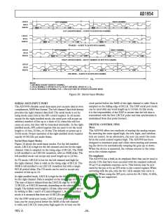
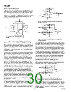
NOTES
1. DSP MODE DOESN’T IDENTIFY CHANNEL.
2. LRCLK NORMALLY OPERATES AT fS EXCEPT DSP MODE, WHICH IS 2 fS.
3. BCLK FREQUENCY IS NORMALLY 64 LRCLK BUT MAY BE OPERATED IN BURST MODE.
Figure 20. Serial Input Modes
clock period before the MSB of the right channel is valid. Data is
sampled on the falling edge of BCLK.The DSP serial port mode
can be used with any word length up to 24 bits. In this mode,
it is the responsibility of the DSP to ensure that the left data is
transmitted with the first LRCLK pulse and that synchronism is
maintained from that point forward.
The AD1954’s flexible serial data input port accepts data in twos
complement, MSB first format.The left channel data field always
precedes the right channel data field.The serial mode is set by
using mode select bits in the SPI control register. In all modes
except for the right-justified mode, the serial port will accept an
arbitrary number of bits up to a limit of 24 (extra bits will not
cause an error, but they will be truncated internally). In the right-
justified mode, SPI control register bits are used to set the word
length to 16 bits, 20 bits, or 24 bits.The default on power-up is
24-bit mode. Proper operation of the right-justified mode requires
exactly 64 BCLKs per audio frame.
DIGITAL CONTROL PINS
Mute
The AD1954 offers two methods of muting the analog output.
By asserting the mute signal high, the left, right, and subchan-
nels are muted. As an alternative, the user can assert the mute
bit in the serial control register high. The AD1954 has been
designed to minimize pops and clicks when muting and unmut-
ing the device by automatically ramping the gain up or down.
When the device is unmuted, the volume returns to the value
set in the volume register.
Serial Data Input Modes
Figure 20 shows the serial input modes. For the left-justified
mode, LRCLK is high for the left channel and low for the right
channel. Data is sampled on the rising edge of BCLK.The MSB
is left-justified to an LRCLK transition, with no MSB delay.The
left-justified mode can accept any word length up to 24 bits.
De-emphasis
The AD1954 has a built-in de-emphasis filter that can be used to
decode CDs that have been encoded with the standard redbook
50 µs/15 µs emphasis response curve.This feature may be acti-
vated by the pin or by an SPI write to the control register.When
activating with the pin, only the 44.1 kHz sample rate curve is
available.When using the SPI port, curves for 44.1 kHz, 32 kHz,
and 48 kHz are supported.
In I
2S mode, LRCLK is low for the left channel and high for the right channel. Data is valid on the rising edge of BCLK.The
MSB is left-justified to an LRCLK transition but with a single
BCLK period delay.The I2S mode can be used to accept any
number of bits up to 24.
In right-justified mode, LRCLK is high for the left channel and low
for the right channel. Data is sampled on the rising edge of BCLK.
The start of data is delayed from the LRCLK edge by 16 BCLK,
12 BCLK, or 8 BCLK intervals, depending on the selected word
length.The default word length is 24 bits; other word lengths are set
by writing to Bits 1 and 0 of Control Register 1. In right-justified
mode, it is assumed that there are 64 BCLKs per frame.
For the DSP serial port mode, LRCLK must pulse high for at
least one bit clock period before the MSB of the left channel
is valid, and LRCLK must pulse high again for at least one bit
REV. A

 ADI [ ADI ]