3.01k
1.50k
270pF
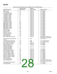
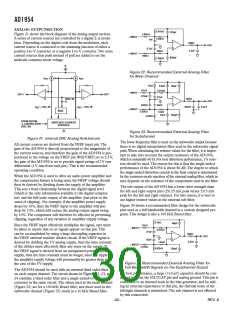
Figure 21 shows the block diagram of the analog output section.
A series of current sources are controlled by a digital -
modu-
lator. Depending on the digital code from the modulator, each
current source is connected to the summing junction of either a
positive I-to-V converter or a negative I-to-V converter.Two extra
current sources that push instead of pull are added to set the
midscale common-mode voltage.
2.80k
1nF
– INPUT
+ INPUT
549
OUT
2.7nF
806
2.2nF
499
820pF
1.00k
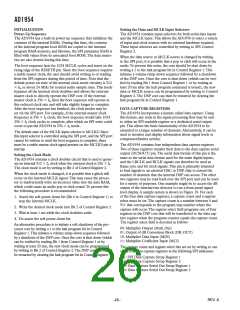
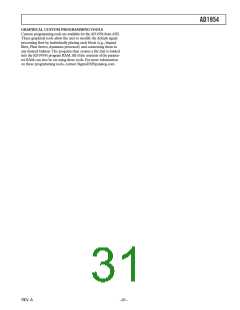
Figure 22. Recommended External Analog Filter
for Main Channel
I
I
REF
REF
11k
6.8nF
68pF
11k
3.01k
– INPUT
+ INPUT
OUT+
OUT–
270nF
27nF
56nF
604
VREF IN
OUT
560nF
2.2nF
I
+ DIG_IN
I
– DIG_IN
220nF
REF
REF
BIAS
5.62k
1.5k
15nF
150pF
5.62k
FROM DIGITAL
SWITCHED CURRENT
SOURCES
- MODULATOR
(DIG_IN)
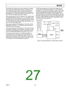
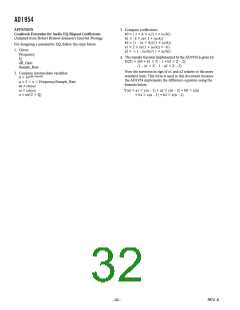
Figure 23. Recommended External Analog Filter
for Subchannel
Figure 21. Internal DAC Analog Architecture
The lower frequency filter is used on the subwoofer output because
there is no digital interpolation filter used in the subwoofer signal
path.When calculating the resistor values for the filter, it is impor-
tant to take into account the output resistance of the AD1954,
which is nominally 60 . For best distortion performance, 1% resis-
tors should be used.The reason for this is that the single-ended
performance of the AD1954 is about 80 dB.The degree to which
the single-ended distortion cancels in the final output is determined
by the common-mode rejection of the external analog filter, which in
turn depends on the tolerance of the components used in the filter.
All current sources are derived from theVREF input pin.The
gain of the AD1954 is directly proportional to the magnitude of
the current sources, and therefore the gain of the AD1954 is pro-
portional to the voltage on theVREF pin.WithVREF set to 2.5V,
the gain of the AD1954 is set to provide signal swings of 2V rms
differential (1V rms from each pin).This is the recommended
operating condition.
When the AD1954 is used to drive an audio power amplifier and
the compression feature is being used, theVREF voltage should
then be derived by dividing down the supply of the amplifier.
This sets a fixed relationship between the digital signal level
(which is the only information available to the digital compres-
sor) and the full-scale output of the amplifier (just prior to the
onset of clipping). For example, if the amplifier power supply
drops by 10%, then theVREF input to the amplifier will also
drop by 10%, which will reduce the analog output signal swing
by 10%.The compressor will therefore be effective in preventing
clipping, regardless of any variation in amplifier supply voltage.
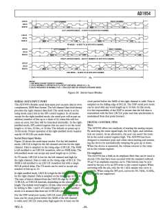
The sub output of the AD1954 has a lower drive strength than
the left and right output pins (±0.25 mA peak versus ±0.5 mA
peak for the left and right outputs). For this reason, it is best to
use higher resistor values in the external sub filter.
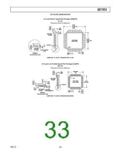
Figure 24 shows a recommended filter design for the subwoofer
pins used as a full bandwidth channel in a custom designed pro-
gram.This design is also a 100 kHz Bessel filter.
11k
68pF
Since theVREF input effectively multiplies the signal, care must
be taken to ensure that no ac signals appear on this pin.This
can be accomplished by using a large decoupling capacitor in
theVREF external resistive divider circuit. If theVREF signal is
derived by dividing the 5V analog supply, then the time constant
of the divider must effectively filter any noise on the supply. If
theVREF signal is derived from an unregulated power amplifier
supply, then the time constant must be longer, since the ripple on
the amplifier supply voltage will presumably be greater than in
the case of the 5V supply.
11k
– INPUT
3.01k
27nF
604
OUT
56nF
2.2nF
1.5k
5.62k
+ INPUT
5.62k
150pF
Figure 24. Recommended External Analog Filter for
Full Bandwidth Signals on the Subchannel Output
The AD1954 should be used with an external third order filter
on each output channel.The circuit shown in Figures 22, 23, and
24 combine a third order filter and a single-ended-to-differential
converter in the same circuit
.
T
he values used in the main channel
(Figure 22) are for a 100 kHz Bessel filter, and those used in the
subwoofer channel (Figure 23) result in a 10 kHz Bessel filter.
For best performance, a large (>10 µF) capacitor should be con-
nected between the FILTCAP pin and analog ground.This pin is
connected to an internal node in the bias generator, and by add-
ing an external capacitance to this pin, the thermal noise of the
left/right channels is minimized.The sub channel is not affected
by this connection.
REV. A

 ADI [ ADI ]