Bit 8 is used to enable the three serial output pins.These pins are
connected to the output of the serial input mux, which is set by
Bits 7 and 6.The default is 0 (disabled).
1. Direct
read/write
.
T
his method allows direct access to the
RAMs. Since the RAMs are also being used during real-time
DSP operation, a glitch will likely occur at the output.This
method is not recommended.
Bit 9 changes the default setting of the volume ramp speed.When
set to 0, it will take 1024 LRCLK periods to go from full volume
(6 dB) to infinite attention.When set to 1, the same operation
will take 8192 LRCLK periods.
2. Direct
read/write after core shutdown
.
T
his method avoids
the glitch while accessing the internal RAMs by first shutting
down the core.This is recommended for transferring large
amounts of data, such as initializing the parameter RAM at
power-up or downloading a completely new program.These
transfers can be sped up by using burst mode, where an initial
address followed by blocks of data are sent to the RAM.
Volume Registers
The AD1954 contains three 22-bit volume registers: one each for
the left, right, and subwoofer channels.These registers are special
because when the volume is changed from an initial value to a
new value, a linear ramp is used to interpolate between the two
values.This feature prevents audible clicks and pops when chang-
ing volume.The ramp is set so that it takes 512 audio frames to
decrement from a volume of 1.0 (default) down to 0 (muted).
The volume registers are formatted in 2.20 twos complement,
meaning that 0100000000000000000000 is interpreted as 1.0.
Negative values can also be written to the volume register, caus-
ing an inversion of the signal. Negative values work as expected
with the ramp feature; to go from +1.0 to –1.0 will take 1024
LRCLKs, and the volume will pass through 0 on the way.
3. Safeload writes.This is where up to five SPI registers are loaded
with address/data intended for the parameter RAM.The data
is then transferred to the requested address when the RAM is
not busy.This method can be used for dynamic updates while
live program material is playing through the AD1954. For
example, a complete update of one biquad section can occur in
one audio frame while the RAM is not busy.This method is not
available for writing to the program RAM or control registers.
The next section discusses these options in more detail.
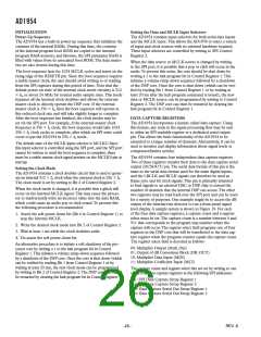
Soft Shutdown Mechanism
Parameter RAM Contents
When writing large amounts of data to the program or parameter
RAM, the processor core should be halted to prevent unpleasant
noises from appearing at the audio output. Figure 18 shows a
graphical representation of this mechanism’s volume envelope.
Points A through D are referenced in the following description.
Bit 10 in Serial Control Register 0 (processor shutdown bit) will
shut down the processor core.When the processor shutdown bit
is asserted (A), an automatic volume ramp-down sequence
(B) lasting from 10 ms to 20 ms will occur, followed by a shut-
down of the core.This method of shutting down the core
prevents pops or clicks from occurring. After the shutdown is
complete, Bit 1 in Control Register 1 will be set.The user can
either poll for this bit to be set or just wait for a period longer
TableVI shows the contents of the parameter RAM for the AD1954’s
default program.The parameter RAM is 22 bits wide and occupies
SPI Addresses 0 through 255.The low addresses of the RAM are
used to control the biquad filters.There are 22 biquad filters in all,
and each biquad has five coefficients, resulting in a total memory
usage of 110 coefficients.There are also two tables of 33 coeffi-
cients, each that define the main and subcompressor input/output
characteristics.These are loaded with 1.0 on power-up, resulting
in no compression. Other RAM entries control other compressor
characteristics, as well as delay and spatialization settings.
The parameter RAM is initialized on power-up by an on-board
boot ROM.The default values yield no equalization, no com-
pression, no spatialization, no delay, and normal detector time
constants in the compressor sections.The functionality of the
AD1954 on power-up is basically that of a normal audio DAC
with no signal processing capability.
Once the core is shut down (C), the parameter or program RAMs
may be written or read freely.To facilitate the transfer of large
blocks of sequential data, a block transfer mode is supported
where a starting address followed by a stream of data is sent to the
memory.The address into the memory will be automatically
incremented for each new write
.
T
his mode is documented in the
SPI Read/Write Data Formats section of this data sheet.
The data format of the parameter RAM is twos complement
2.20 format.This means that the coefficients may range from
+2.0 (–1 LSB) to –2.0, with 1.0 represented by the binary word
Options for Parameter Updates
The parameter and program RAMs can be written and read using
Once the data has been written, the shutdown bit can be cleared
(D).The processor then will initiate a volume ramp-up sequence
A
B
C
D
Figure 18. Recommended Sequences for Complete Parameter or Program RAM Uploaded Using Shutdown Mechanism
REV. A

 ADI [ ADI ]