Device Architecture
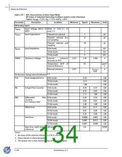
Table 2-47 • ADC Characteristics in Direct Input Mode
All Values at Industrial Operating Conditions (unless noted otherwise)
Typical: VCC33A = 3.3 V, VCC = 1.5 V, and TA = 25°C
Parameter
Description Condition
Minimum
Typical
Maximum
Units
All Analog Inputs
VINADC
Input Voltage (direct to Refer to Table 3-2 on
ADC)
page 3-3.
CINADC
Input Capacitance
Channel not selected
7
8
pF
pF
Channel selected but
not sampling
Channel selected and
sampling
18
pF
ZINADC
VAREF
Input Impedance
Reference Voltage
8-bit mode
10-bit mode
12-bit mode
2
2
kΩ
kΩ
kΩ
V
2
Internal
Accuracy at 25°C
reference
2.537
2.527
2.56
2.583
Temperature Drift of
Internal Reference
65
ppm/°
C
External reference
VCC33A
0.05
+
V
DC Accuracy (using external reference)1, 2
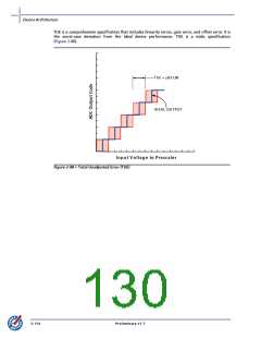
TUE
Total Unadjusted Error
8-bit mode
10-bit mode
12-bit mode
8-bit mode
10-bit mode
12-bit mode
0.29
0.72
1.80
0.20
0.32
1.71
0.20
0.60
2.40
0.01
0.05
0.20
0.0004
0.002
0.007
2.0
LSB
LSB
LSB
LSB
LSB
LSB
LSB
LSB
LSB
LSB
LSB
LSB
LSB
LSB
LSB
%FSR
INL
Integral Non-Linearity
0.25
0.43
1.80
0.24
0.65
2.48
0.17
0.20
0.40
0.003
0.011
0.044
DNL
Differential
Linearity
(no missing codes)
Non- 8-bit mode
10-bit mode
12-bit mode
8-bit mode
Offset Error
Gain Error
10-bit mode
12-bit mode
8-bit mode
10-bit mode
12-bit mode
Gain Error (with internal All modes
reference)
Notes:
1. Accuracy of the external reference is 2.56 V 4.6 mV.
2. Data is based on characterization.
3. The sample rate is time-shared among active analog inputs.
2-118
Preliminary v1.7

 ACTEL [ Actel Corporation ]