Device Architecture
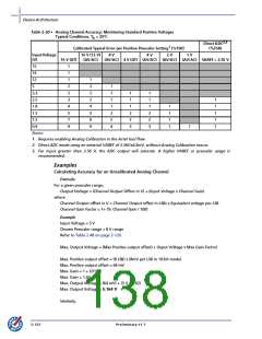
Table 2-50 • Analog Channel Accuracy: Monitoring Standard Positive Voltages
Typical Conditions, TA = 25°C
Direct ADC2,3
(%FSR)
Calibrated Typical Error per Positive Prescaler Setting1 (%FSR)
InputVoltage
(V)
16 V (12 V)
(AV/AC)
8 V
4 V
2 V
1 V
16 V (AT)
(AV/AC) 4 V (AT) (AV/AC) (AV/AC) (AV/AC) VAREF = 2.56 V
15
1
1
1
2
2
3
4
5
7
9
14
12
1
2
2
2
4
5
6
9
5
1
3.3
2.5
1.8
1.5
1.2
0.9
Notes:
1
1
1
2
2
4
1
1
1
2
2
3
1
1
1
2
2
3
1
1
1
1
1
1
1
1
1
1
1. Requires enabling Analog Calibration in the Actel tool flow.
2. Direct ADC mode using an external VAREF of 2.56V 4.6mV, without Analog Calibration macro.
3. For input greater than 2.56 V, the ADC output will saturate. A higher VAREF or prescaler usage is
recommended.
Examples
Calculating Accuracy for an Uncalibrated Analog Channel
Formula
For a given prescaler range,
Output Voltage = (Channel Output Offset in V) + (Input Voltage x Channel Gain)
where
Channel Output offset in V = Channel Output offset in LSBs x Equivalent voltage per LSB
Channel Gain Factor = 1+ (% Channel Gain / 100)
Example
Input Voltage = 5 V
Chosen Prescaler range = 8 V range
Refer to Table 2-48 on page 2-120.
Max. Output Voltage = (Max Positive output offset) + (Input Voltage x Max Gain Factor)
Max. Positive output offset = (8 LSB) x (8mV per LSB in 10-bit mode)
Max. Positive output offset = 64 mV
Max. Gain = 1 + (2/100)
Max. Gain = 1.02
Max. Output Voltage = (64 mV) + (5 V x 1.02)
Max. Output Voltage = 5.164 V
Similarly,
2-122
Preliminary v1.7

 ACTEL [ Actel Corporation ]