FEDL87V2107-01
OKI Semiconductor
ML87V2107
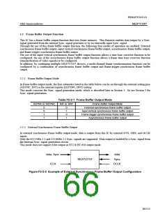
2.2.3 Input Vertical Synchronous Frame Buffer Output Mode
In input vertical synchronous frame buffer output mode, data is output from this IC by generating output system Sync.
signals (OVS, OHS) out of the input system vertical Sync. signal (IVS) and OCLK.
External input or crystal oscillation can be selected as OCLK.
Only the 625/50Hz 2:1 and 525/60Hz 2:1 Sync. signals are generated by this IC. Using IVS as the reference (starting
point), OVS can be generated at any position by register setting. The phase difference between IVS and OVS is
always constant.
Using IVS as the reference (starting point), OHS is generated by dividing OCLK, so that data output is enabled by the
stable standard horizontal Sync. signal. This will bring about the time base corrector effect.
However, if ICLK is asynchronous with OCLK, input-output phase errors are corrected in the last valid line. So it is
possible that the standard horizontal Sync. signal period cannot be fulfilled.
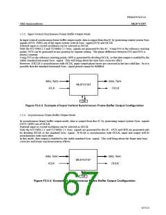
data, Sync.
ICLK
data, Sync.
OCLK
ML87V2107
CX
Figure F2-2-3 Example of Input Vertical Synchronous Frame Buffer Output Configuration
2.2.4 Asynchronous Frame Buffer Output Mode
In asynchronous frame buffer output mode, data is output from this IC by generating output system Sync. signals
(OVS, OHS) out of OCLK.
External input or crystal oscillation can be selected as OCLK.
Only the 625/50Hz 2:1 and 525/60Hz 2:1 Sync. signals are generated by this IC. OVS and OHS are generated only
by dividing OCLK as the standard Sync. signal. If ICLK is asynchronous with OCLK, input and output will be
asynchronous with each other.
In this mode, data output is enabled by the stable standard Sync. signal. This will bring about the frame time base
corrector and frame synchronoization effects.
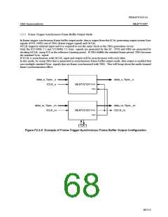
data, Sync.
ICLK
data, Sync.
OCLK
ML87V2107
CX
Figure F2-2-4 Example of Asynchronous Frame Buffer Output Configuration
67/152

 OKI [ OKI ELECTRONIC COMPONETS ]