FEDL87V2107-01
OKI Semiconductor
ML87V2107
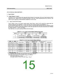
1.1.3 Setting Input System Valid Area
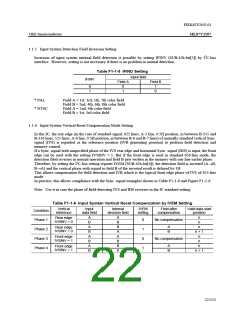
This IC generates the write enable signals (IWE) for writing data in the valid area made up of the valid vertical
lines and the valid horizontal pixels defined by the input control mode settings to the frame memory.
With the write enable, it is possible to set the starting point in the vertical and horizontal directions. This setting
makes it possible to position the areas of valid lines and valid pixels with non-standard phase Sync. signals.
This IC also generates a Read Enable (IRE) signal for Read operation to establish recursive noise reduction.
Normally, the valid number of lines that can be written to the memory is 288/243. However, by setting VBID
(SUB:41h-bit[3]) = 1 in ITU-R BT.656 mode, 304/254 lines can be selected as the valid number of lines.
However, the valid number of lines for noise reduction processing remains 288/243.
In 525i mode, normally the valid number of lines is 288/243. However, by setting AR241 (SUB:72h-bit[4]) = 1,
the valid number of lines can be restricted to only 241 by disabling two lines of valid noise reduction processing
lines from the top.
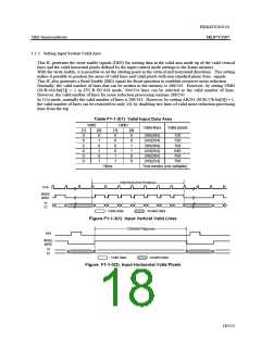
Table F1-1-3(1) Valid Input Data Area
VMD
HMD
Valid lines
Valid pixels
[1]
0
[0]
0
[1]
0
[0]
0
288(304)
243(254)
288(304)
243(254)
288(304)
243(254)
720
720
768
640
768
768
0
1
0
0
0
0
0
1
0
1
0
1
0
0
1
0
0
1
1
0
Other
Test modes (not settable)
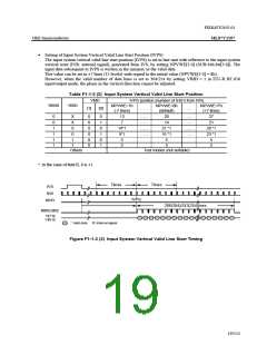
288(304)/243(254)lines
IHS
#IWE
#IRE
YI
CI
: Valid data
: Invalid data
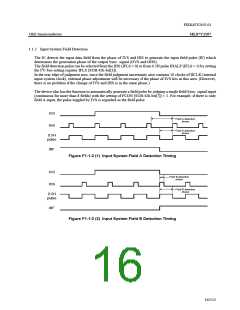
Figure F1-1-3(1) Input Vertical Valid Lines
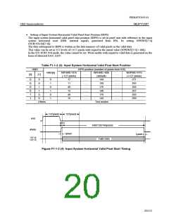
720/640/768pixels
IHS
#IWE
#IRE
YI
CI
: Valid data
: Invalid data
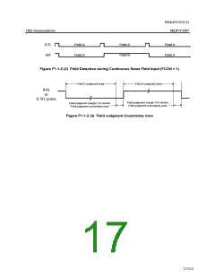
Figure F1-1-3(2) Input Horizontal Valid Pixels
18/152

 OKI [ OKI ELECTRONIC COMPONETS ]