EM785830AA
8-bit Micro-controller
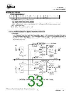
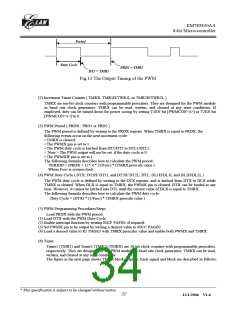
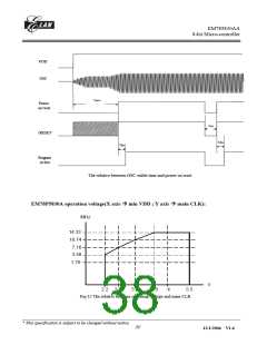
Period
Duty Cycle
PRD1 = TMR1
DT1 = TMR1
Fig.13 The Output Timing of the PWM
(2) Increment Timer Counter ( TMRX: TMR1H/TWR1L or TMR2H/TWR2L )
TMRX are ten-bit clock counters with programmable prescalers. They are designed for the PWM module
as baud rate clock generators. TMRX can be read, written, and cleared at any reset conditions. If
employed, they can be turned down for power saving by setting T1EN bit [PWMCON<4>] or T2EN bit
[PWMCON<5>] to 0.
(3) PWM Period ( PRDX : PRD1 or PRD2 )
The PWM period is defined by writing to the PRDX register. When TMRX is equal to PRDX, the
following events occur on the next increment cycle:
• TMRX is cleared.
• The PWMX pin is set to 1.
• The PWM duty cycle is latched from DT1/DT2 to DTL1/DTL2.
< Note > The PWM output will not be set, if the duty cycle is 0;
• The PWMXIF pin is set to 1.
The following formula describes how to calculate the PWM period:
PERIOD = (PRDX + 1) * 4 * (1/Fosc) * (TMRX prescale value )
Where Fosc is system clock
(4) PWM Duty Cycle ( DTX: DT1H/ DT1L and DT2H/ DT2L; DTL: DL1H/DL1L and DL2H/DL2L )
The PWM duty cycle is defined by writing to the DTX register, and is latched from DTX to DLX while
TMRX is cleared. When DLX is equal to TMRX, the PWMX pin is cleared. DTX can be loaded at any
time. However, it cannot be latched into DTL until the current value of DLX is equal to TMRX.
The following formula describes how to calculate the PWM duty cycle:
Duty Cycle = (DTX) * (1/Fosc) * (TMRX prescale value )
(5) PWM Programming Procedures/Steps
Load PRDX with the PWM period.
(1) Load DTX with the PWM Duty Cycle.
(2) Enable interrupt function by writing IOCF PAFE0, if required.
(3) Set PWMX pin to be output by writing a desired value to IOCC PAGE0.
(4) Load a desired value to R5 PAGE3 with TMRX prescaler value and enable both PWMX and TMRX.
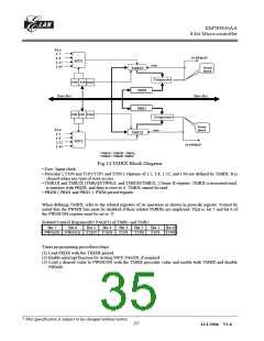
(6) Timer
Timer1 (TMR1) and Timer2 (TMR2) (TMRX) are 10-bit clock counters with programmable prescalers,
respectively. They are designed for the PWM module as baud rate clock generators. TMRX can be read,
written, and cleared at any reset conditions.
The figure in the next page shows TMRX block diagram. Each signal and block are described as follows:
__________________________________________________________________________________________________________________________________________________________________
* This specification is subject to be changed without notice.
32
12/1/2004 V1.6

 ELAN [ ELAN MICROELECTRONICS CORP ]